
OLED screen sub-pixel brightness extraction method based on imaging brightness meter

An extraction method and sub-pixel technology, applied in instruments, static indicators, etc., can solve the problems of DeMura failure, unsatisfactory shooting and drawing, etc., to avoid periodic deviation, save calculation amount, and solve the problem of moiré. Effect

Active Publication Date: 2021-10-01
苇创微电子上海有限公司
View PDF5 Cites 7 Cited by
  • Summary
  • Abstract
  • Description
  • Claims
  • Application Information

AI Technical Summary

Problems solved by technology

Ideal shooting and drawing can accurately obtain the display characteristics (inconsistency) of each sub-pixel, but unsatisfactory shooting and drawing will often lead to the failure of DeMura

Method used


Image

  • OLED screen sub-pixel brightness extraction method based on imaging brightness meter
  • OLED screen sub-pixel brightness extraction method based on imaging brightness meter
  • OLED screen sub-pixel brightness extraction method based on imaging brightness meter

Examples


Embodiment 1

[0078] This embodiment specifically illustrates the process of moiré generation, and the specific implementation process is as follows:

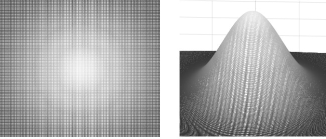
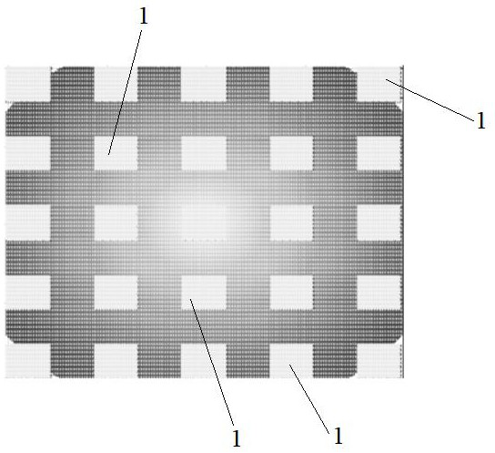
[0079] First, for a sub-pixel on the display screen to be tested (simplified as a point light source), it passes through the optical system (lens group, etc.) of the imaging luminance meter to form an image on the sensor of the imaging luminance meter. for maximum clarity. But all optical systems have certain non-idealities. Therefore, usually the image is not a point like its light source, but diffused into a bright spot. Usually this is a circle of confusion that fits a two-dimensional normal distribution, such as figure 1 As shown, while the circle of confusion falls on the sampling point of the sensor of the imaging luminance meter, the position may be different. Such as figure 2 As shown, the sampling area 1 of the imaging luminance meter is the actual sampling area of ​​the sampling points of the imaging luminance meter, and its re...

Embodiment 2

[0100] This embodiment is a method for extracting brightness of OLED screen sub-pixels based on imaging luminance meter provided by the present invention, such as Figure 5 shown, including the following steps:

[0101] S1: Adjust the focal length, position and exposure time of the imaging luminance meter, and take pictures output by the display screen to be tested, so that the maximum luminance value acquired by the imaging luminance meter is within a preset brightness range. Wherein, the upper limit of the preset brightness range does not exceed 90% of the upper limit of the brightness range of the imaging luminance meter.

[0102] In this embodiment, a 101M Mono camera is used to shoot an OLED screen with a resolution of 2160*1080; , to obtain an image with a length of 10,000 pixels (sampling points) and a width of 5,000 pixels (sampling points). When the exposure time is 320ms, the obtained maximum brightness value is 153.

[0103]S2: Obtain the spatial sampling magnific...


PUM


Abstract

The invention discloses an OLED screen sub-pixel brightness extraction method based on an imaging brightness meter. The OLED screen sub-pixel brightness extraction method comprises the steps of shooting a picture output by a display screen to be detected; obtaining a spatial sampling multiplying power K; segmenting the image into a plurality of sub-pixel groups, and performing curved surface fitting to obtain a dispersion coefficient or an average value thereof; performing simulation by using the two-dimensional dispersion model to obtain a simulated dispersion circle, and calculating corresponding simulated sampling groups for different sampling positions; and matching the sampling position, and performing fitting calculation according to the sampling position to obtain a fitting brightness value of the center of the simulated confusion circle corresponding to each sub-pixel group, and taking the fitting brightness value as a sub-pixel brightness value of the display screen to be tested. According to the invention, mode matching is carried out for different sampling positions, different fitting is applied for different sampling positions, the brightness of the sub-pixel center of the display screen to be measured is restored, generation of periodic deviation is avoided, the moire problem is essentially solved, generation of moire is avoided, and the measurement precision is improved.

Description

technical field [0001] The invention relates to the field of display manufacturing, in particular to a method for extracting luminance of OLED screen sub-pixels based on an imaging luminance meter. Background technique [0002] In the existing technology, the use of current-driven self-luminous displays (including OLED displays, MiniLED displays, and future MicroLED displays) will produce circuit inconsistencies at the sub-pixel level due to limitations in the manufacturing process. This inconsistency is manifested in the display, which is a kind of overall or partial display inhomogeneity, which is manifested as block, sand, point, etc., and this inhomogeneity is collectively called Mura (referring to the uneven brightness of the display, which causes various trace phenomena). Mura usually has two types of brightness Mura and color Mura, indicating the unevenness of brightness and color. At present, Mura is one of the main factors limiting the yield of domestic OLED produc...

Claims


Application Information

Patent Timeline
Patent Type & Authority Applications(China)
IPC IPC(8): G09G3/20G09G3/3208
CPCG09G3/2074G09G3/3208
Inventor 蔡剑李堃叶选新蔡杰羽石炳磊白海楠朱诗文
Owner 苇创微电子上海有限公司
Learn More