Slurry balance pipe jacking construction method

A mud-water balance and construction method technology, applied in pipeline laying and maintenance, pipes/pipe joints/fittings, mechanical equipment, etc., can solve problems such as poor results, and achieve the effect of reducing jacking force and friction

Pending Publication Date: 2021-10-01
RAILWAY NO 5 BUREAU GRP FIRST ENG CO LTD +2
View PDF5 Cites 0 Cited by
  • Summary
  • Abstract
  • Description
  • Claims
  • Application Information

AI Technical Summary

Problems solved by technology

In the mud-water balance pipe jacking construction, in order to reduce the frictional resistance during the jacking process, the method of evenly brushing industrial paraffin on the outer wall of the pipe is usually adopted in many places. Although this method can reduce the frictional resistance during the jacking process, but it doesn't work very well

Method used


Image

  • Slurry balance pipe jacking construction method
  • Slurry balance pipe jacking construction method
  • Slurry balance pipe jacking construction method

Examples


Embodiment 1

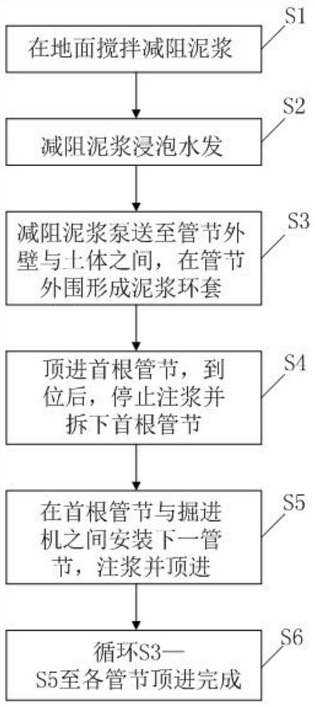
[0032] This embodiment provides a mud-water balance pipe jacking construction method, and the mud-water balance pipe jacking includes a plurality of pipe joints, such as figure 1 As shown, the method includes the following steps:

[0033] S1: Stir the drag reducing mud on the ground; the drag reducing mud includes bentonite, soda ash, sodium carboxymethylcellulose and water, bentonite is 17% by weight, soda ash is 1% by weight, sodium carboxymethylcellulose is 0.3% by weight, and water is wt81.7%;

[0034] S2: Soak water in drag-reducing mud;

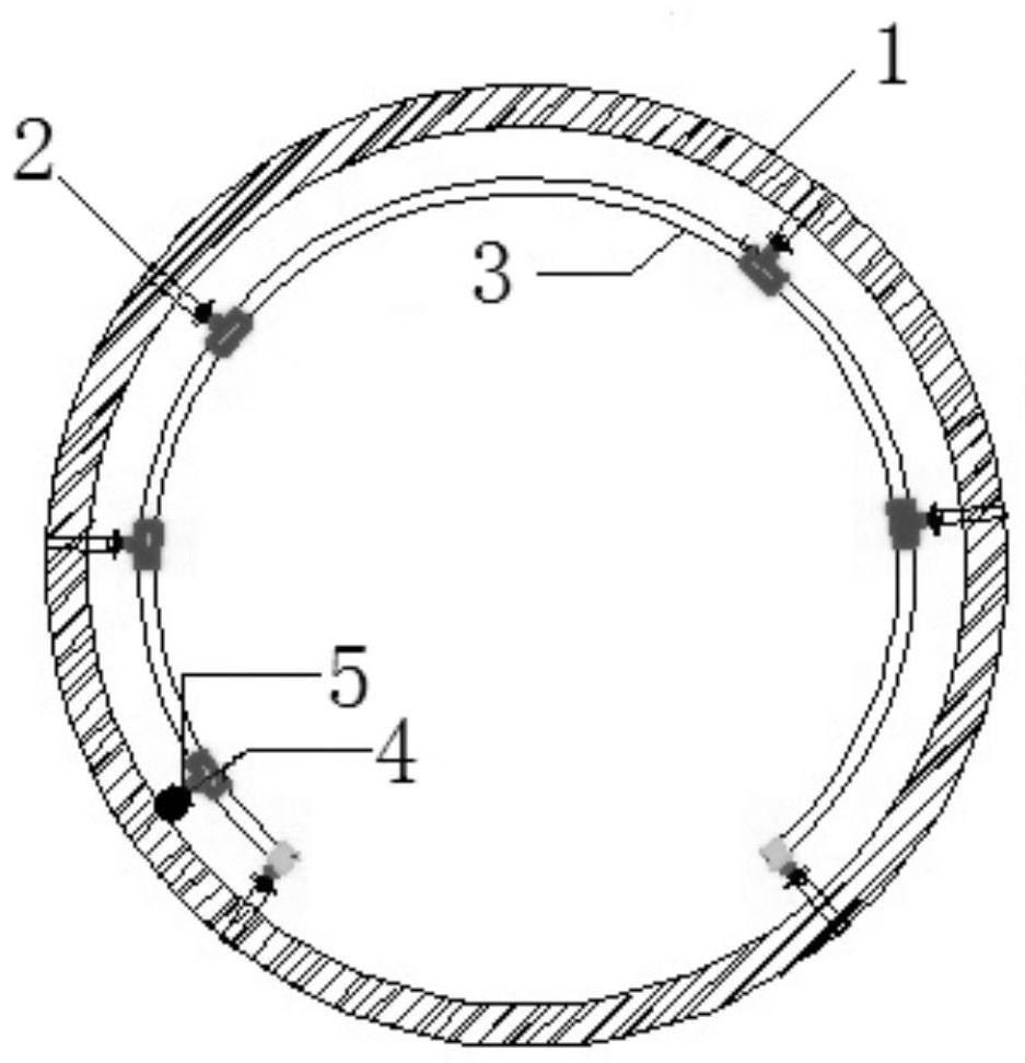
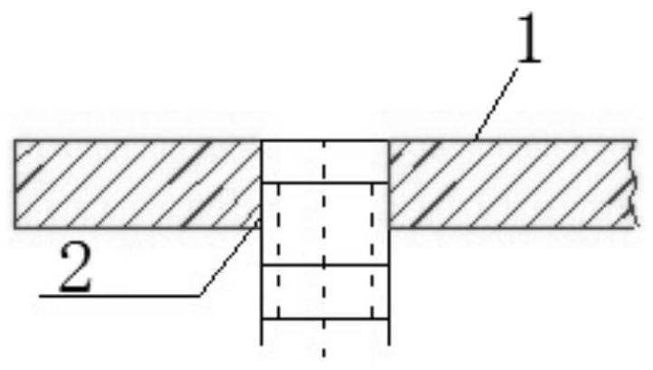
[0035] S3: The drag reducing mud is pumped between the outer wall of the pipe joint 1 and the soil, and a mud ring is formed around the pipe joint 1;

[0036] S4: The first pipe section 1 is jacked in, and when it is in place, stop grouting and remove the first pipe section 1;

[0037] S5: install the next pipe section 1 between the first pipe section 1 and the roadheader, inject grout and jacking;

[0038] S6: Cycle S3-S5 until the...

Embodiment 2

[0046] This embodiment provides a mud-water balance pipe jacking construction method. The difference from Embodiment 1 is that bentonite is wt13%, soda ash is wt0.5%, sodium carboxymethylcellulose is wt0.1%, and water is wt86. 4%.

Embodiment 3

[0048]This embodiment provides a mud-water balance pipe jacking construction method. The difference from Embodiment 1 and Embodiment 2 is that bentonite is wt15%, soda ash is wt0.8%, and sodium carboxymethylcellulose is wt0.2%. Water is wt84%.

[0049] The following table has provided the relationship between the slurry proportioning and the coefficient of friction in Embodiment 1, Embodiment 2, Embodiment 3 and other situations, as can be seen from it, bentonite is 13wt%-17wt%, and soda ash is 0.5wt%- 1 wt%, sodium carboxymethyl cellulose 0.1 wt%-0.3 wt%, and the balance being water, the drag reduction effect is better.

[0050] Serum ratio

[0051]

[0052]


PUM


Abstract

The invention discloses a slurry balance pipe jacking construction method. A slurry balance jacking pipe comprises a plurality of pipe joints, and the method comprises the following steps: anti-drag slurry is stirred on the ground, the anti-drag slurry comprises 13 wt%-17 wt% of bentonite, 0.5 wt%-1 wt% of sodium carbonate, 0.1 wt%-0.3 wt% of sodium carboxymethyl cellulose and the balance of water; soaking is carried out in anti-drag slurry and and in water; the anti-drag slurry is pumped between the outer wall of the pipe joint and the soil body, and a slurry ring sleeve is formed on the periphery of the pipe joint; the first pipe joint is jacked in place, grouting is stopped, and the first pipe joint is detached; a next pipe joint is installed between the first pipe joint and a heading machine, and grouting and jacking are conducted; and circulation is conducted till jacking of all the pipe joints is completed. A certain amount of anti-drag slurry is injected into the outer wall of the pipeline through the grouting holes in the pipe joints, the slurry ring sleeve is formed on the periphery of the pipeline, the friction force between the outer wall of the pipe joint and a soil layer is reduced, and therefore the jacking force during jacking is reduced.

Description

technical field [0001] The invention relates to the technical field of pipe jacking construction, in particular to a mud-water balance pipe jacking construction method. Background technique [0002] The mud-water balance pipe jacking construction is a mechanical and automatic pipe jacking construction method that cuts the soil body at a full section, uses mud-water pressure to balance the earth pressure and groundwater pressure, and uses mud-water as the medium for transporting spoil. The mud-water balance pipe jacking system is mainly composed of a pipe jacking head, a ground operation platform and other auxiliary equipment. There is a PLC control box inside the machine head, and the ground operation platform sends an action signal to the machine head to control the movement of the machine head. The mud discharge system removes the spoil, the crane lowers the pipe, and the pipe is jacked in sections by the jack. In the mud-water balance pipe jacking construction, in order ...

Claims


Application Information

Patent Timeline
IPC IPC(8): F16L1/036F16L1/06
CPCF16L1/036F16L1/06
Inventor 龙明华周军强李培国苏玉东陈敏汤宇凌涛刘云龙彭学军王满谷钟康杨锡斌胥俊玮徐毅勇雷勇祥段磊杨维童昌林巍杰祝朋飞
Owner RAILWAY NO 5 BUREAU GRP FIRST ENG CO LTD
Why Eureka
Try Eureka