Device for detecting and unloading air pressure of air-tight door

An airtight door, air pressure technology, applied in measuring devices, measuring fluid pressure, special equipment for doors/windows, etc., can solve problems such as difficulty in opening airtight doors, broken airtight doors, etc. damage effect

Inactive Publication Date: 2021-10-01
涂岗
View PDF20 Cites 0 Cited by
  • Summary
  • Abstract
  • Description
  • Claims
  • Application Information

AI Technical Summary

Problems solved by technology

[0005] Aiming at the deficiencies of the prior art, the present invention provides a device for detecting and unloading the air pressure of an airtight door, which is capable of detecting pressure changes on both sides of the airtight door, and when the pressure difference between the inside and outside of the airtight door is large, the device automatically Pressure on both sides, the advantage of improving the service life of the airtight door solves the problem that the airtight door is very difficult to open due to the different air pressure on both sides of the airtight door. At the same time, when the air pressure on both sides of the airtight door A certain limit of super height will cause the airtight door to be squeezed and broken by the air pressure

Method used


Image

  • Device for detecting and unloading air pressure of air-tight door
  • Device for detecting and unloading air pressure of air-tight door
  • Device for detecting and unloading air pressure of air-tight door

Examples


Embodiment Construction

[0023] The following will clearly and completely describe the technical solutions in the embodiments of the present invention with reference to the accompanying drawings in the embodiments of the present invention. Obviously, the described embodiments are only some, not all, embodiments of the present invention. Based on the embodiments of the present invention, all other embodiments obtained by persons of ordinary skill in the art without making creative efforts belong to the protection scope of the present invention.

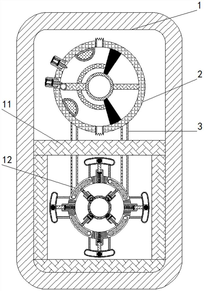
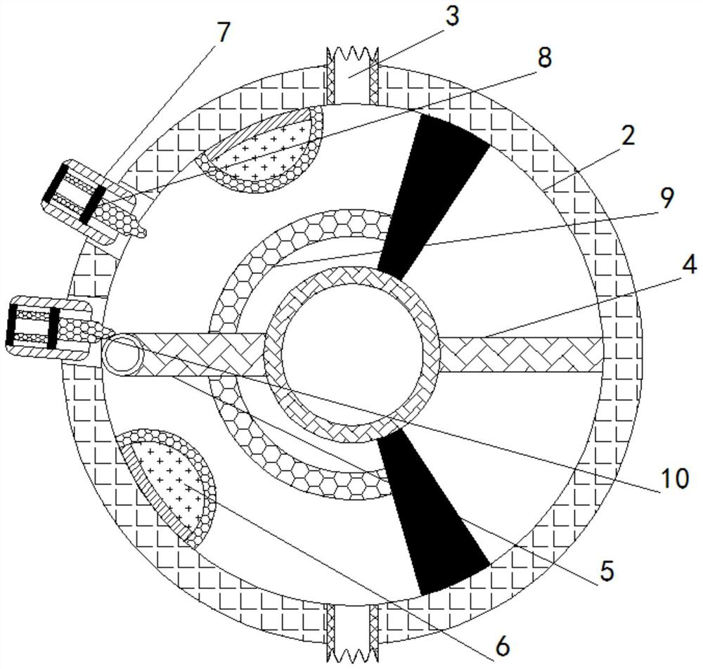
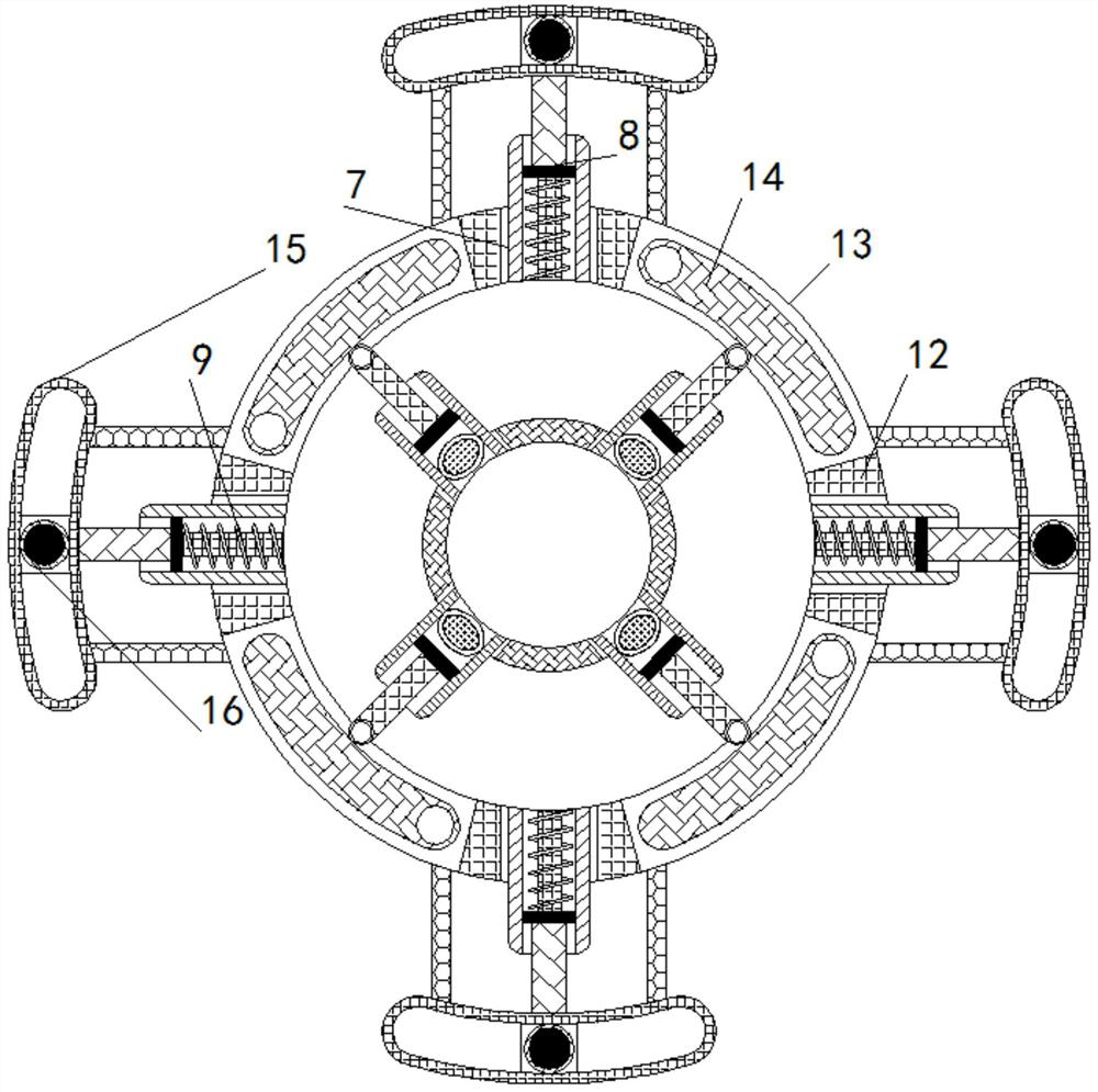
[0024] see Figure 1-4 , a device for detecting air pressure and unloading air pressure for an airtight door, comprising an airtight door main body 1, a fixed disk 2 is fixedly installed inside the airtight door main body 1, and an air guide pipe 3 is fixedly connected to the outer wall of the fixed disk 2, and the air guide The air pipe 3 is connected to the top and bottom of the fixed plate 2, the top air pipe 3 is connected to the outside of the airtight do...


PUM


Abstract

The invention relates to the technical field of air leakage of air-tight doors, and discloses a device for detecting and unloading air pressure of an air-tight door. The device for detecting and unloading the air pressure of the air-tight door comprises an air-tight door body, wherein a fixing disc is fixedly installed in the air-tight door body, an air guiding pipe is fixedly connected to the outer wall of the fixing disc, and a fixing rod is fixedly installed on the inner wall of the fixing disc; the inner wall of the fixing disc is slidably connected with a rotating rod, and an air bag is fixedly installed on the inner wall of the fixing disc. The rotating rod is pushed to deflect through the air pressure difference between the two sides; due to the fact that a convex arc block is arranged in the middle of a buffering plate, the rotating rod cannot pass through the buffering plate and cannot be in contact with the air bag in the fixing disc when the air pressure difference between the two sides is not large; when the air pressure difference between the two sides is large enough, the rotating rod can pass through the buffering plate and extrudes air in the air bag into a circular pipeline to trigger a subsequent mechanism, so that the effect of automatically detecting the air pressure on the inner side and the outer side of the air-tight door is achieved.

Description

technical field [0001] The invention relates to the technical field of airtight door leakage, in particular to a device for detecting and unloading the air pressure of an airtight door. Background technique [0002] The airtight door is a translational set door integrating airtightness, sound insulation, heat preservation, pressure resistance, dustproof, fireproof and radiation protection. It is generally used in hospitals, food factories, industrial plants and other places that require high sound insulation, heat insulation and air tightness. [0003] Due to the different air pressure on the inside and outside of the airtight door, it is very difficult to open the airtight door. At the same time, when the air pressure on both sides of the airtight door exceeds a certain limit, the airtight door will be crushed by the air pressure , so we propose a device for detecting and unloading the air pressure by the airtight door to solve the above problems. Contents of the inventi...

Claims


Application Information

Patent Timeline
Patent Type & Authority Applications(China)
IPC IPC(8): E06B5/12E06B7/02E06B7/28G01L13/00
CPCE06B5/12E06B7/02E06B7/28G01L13/00
Inventor 涂岗
Owner 涂岗
Why Eureka
Try Eureka