Method for conveying objects in pipeline
An object and pipeline technology, applied in the field of object transportation in pipelines, can solve the problems of low efficiency of manual cable laying, high construction cost, long construction period, etc., and achieve the effect of improving laying efficiency, reducing construction period and low cost
- Summary
- Abstract
- Description
- Claims
- Application Information
AI Technical Summary
Problems solved by technology
Method used
Image
Examples
Embodiment 1
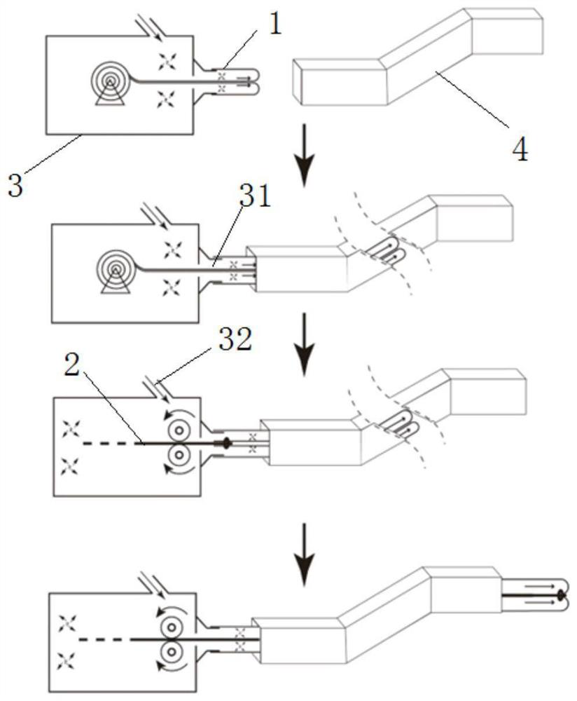
[0040] Such as figure 1 As shown, the object delivery method in the pipeline of this embodiment specifically includes the following steps:
[0041] Step 1) Put the flexible tube 1 with the rear end sealed into the inflatable device 3, make the front end of the flexible tube 1 pass through the outlet 31 of the inflatable device 3, and be sealed with the outlet 31 of the inflatable device; the length of the flexible tube 1 is It is greater than or equal to the length from the entrance of the pipeline 4 to the position to be transported, thereby ensuring that the object to be transported 2 can reach the position to be transported; the front end of the flexible tube 1 is sealed with the outlet 31 of the inflatable device 3 to ensure that the rear faces into the inflatable device 3 The inflated air will not leak, and the air pressure of the inflated gas can be guaranteed to make the flexible tube 1 turn over automatically or more quickly; the seal at the rear end of the flexible tu...
Embodiment 2
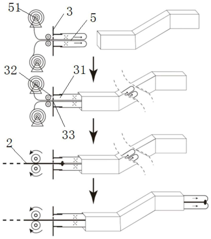
[0049] Such as figure 2 As shown, the object delivery method in the pipeline of this embodiment specifically includes the following steps:
[0050] Step 1) In the inflatable device 3, heat press or bond two layers of strip-shaped films 51 to form a hollow strip-shaped structure 5, seal the rear end of the hollow strip-shaped structure to prevent air leakage at the rear end, and seal the hollow strip-shaped structure. The front end of the shape structure 5 passes through the outlet 31 of the inflator 3, and is sealingly connected with the outlet 31 of the inflator; the length of the strip-shaped film 51 is greater than or equal to the length from the entrance of the pipeline 4 to the position to be transported;
[0051]Step 2) Inflate the inflatable device 3 so that the inner surface of the hollow strip structure 5 continues to turn outward along the exit direction of the pipeline 4 and move forward until the rear end of the hollow strip structure 5 is close to the outlet 31 o...
Embodiment 3
[0057] Such as image 3 As shown, the object delivery method in the pipeline of this embodiment specifically includes the following steps:
[0058] Step 1) heat press or bond two layers of strip-shaped films 51 to form a hollow strip-shaped structure 5, pass the front end of the hollow strip-shaped structure 5 through the inlet 33 and outlet 31 of the inflator 3 in sequence, and place the hollow strip-shaped structure 5 The front end of the structure 5 is sealed and connected to the outlet 31 of the inflator; the length of the strip film 51 is greater than or equal to the length from the inlet of the pipeline 4 to the position to be transported;
[0059] The inlet 33 of the inflator 3 is adapted to the outline of the hollow strip structure 5; thus, to ensure the connection between the inlet of the inflator 3 and the outline of the hollow strip structure 5 during inflation, it can ensure the continuity of the hollow strip structure 5. Move, but also have a certain degree of ai...
PUM
 Abstract
Description
Claims
Application Information
 - Generate Ideas
- Intellectual Property
- Life Sciences
- Materials
- Tech Scout
- Unparalleled Data Quality
- Higher Quality Content
- 60% Fewer Hallucinations
Browse by: Latest US Patents, China's latest patents, Technical Efficacy Thesaurus, Application Domain, Technology Topic, Popular Technical Reports.
© 2025 PatSnap. All rights reserved.Legal|Privacy policy|Modern Slavery Act Transparency Statement|Sitemap|About US| Contact US: help@patsnap.com


