
Temporary storage device for materials

A material and buffer technology, applied in the direction of conveyor objects, transportation and packaging, etc., can solve the problem of unstable material movement, and achieve the effect of symmetrical driving force

Pending Publication Date: 2021-10-01
苏州科韵激光科技有限公司
View PDF0 Cites 0 Cited by
  • Summary
  • Abstract
  • Description
  • Claims
  • Application Information

AI Technical Summary

Problems solved by technology

[0003] The common material buffering station is the station located in the material buffering device, however, the volume of each station is usually determined, therefore, the amount of material used for storage is determined, and in order to cooperate with the material conveying device, the material buffering device The drive unit is used to drive the material to move up and down. This drive unit is usually driven by a single drive unit, which makes the movement of the material less stable.

Method used


Image

  • Temporary storage device for materials
  • Temporary storage device for materials
  • Temporary storage device for materials

Examples


Embodiment Construction

[0033] In order to facilitate the understanding of the present invention, the present invention will be described more fully below with reference to the associated drawings. Preferred embodiments of the invention are shown in the accompanying drawings. However, the present invention can be embodied in many different forms and is not limited to the embodiments described herein. On the contrary, the purpose of providing these embodiments is to make the disclosure of the present invention more thorough and comprehensive.

[0034] It should be noted that when an element is referred to as being “fixed” to another element, it can be directly on the other element or there can also be an intervening element. When an element is referred to as being "connected to" another element, it can be directly connected to the other element or intervening elements may also be present. The terms "vertical," "horizontal," "left," "right," and similar expressions are used herein for purposes of ill...


PUM


Abstract

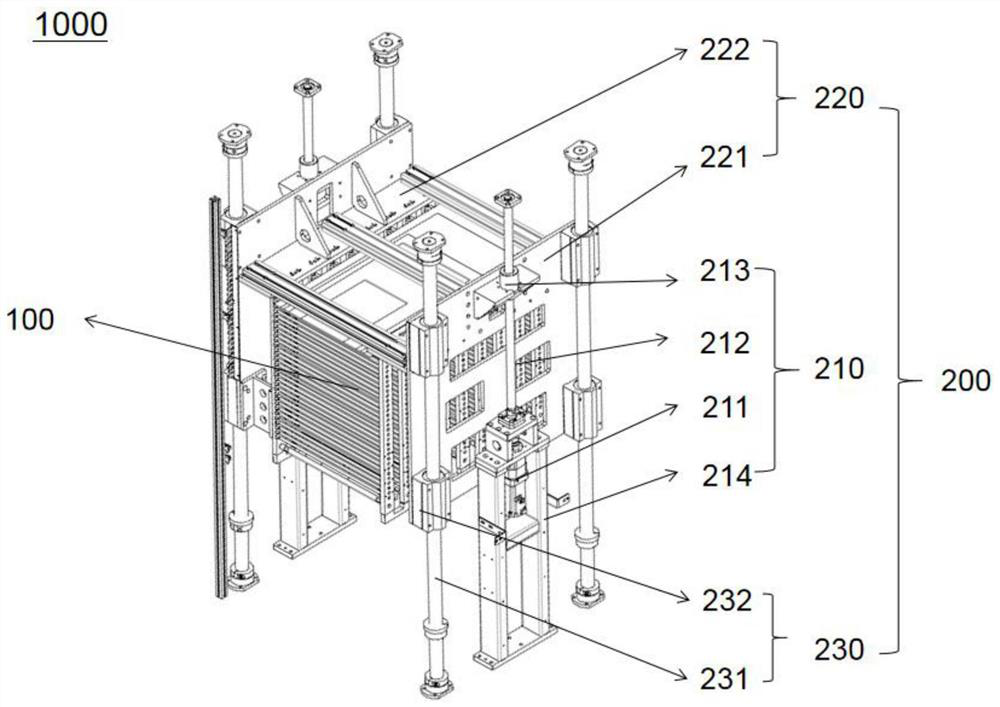
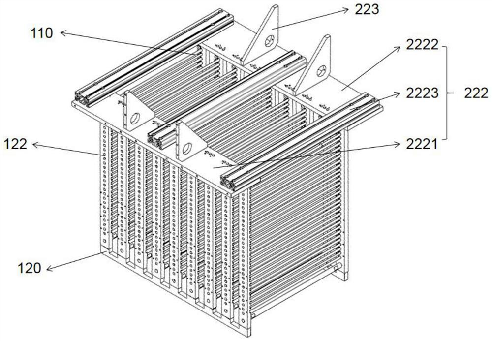
The invention relates to a temporary storage device for materials. The temporary storage device for the materials comprises a material storage mechanism which is used for storing the materials and a driving mechanism which is used for driving the material storage mechanism, the material storage mechanism comprises at least two layers of bearing units used for bearing the materials, the height of the materials which can be borne by the bearing units is changed by changing the distance between the adjacent bearing units, the driving mechanism comprises driving units which are oppositely arranged and located on the two sides of the material storage mechanism, the height of the materials capable of being borne by the bearing units is changed by changing the distance between the adjacent bearing units, and therefore the number of the materials capable of being borne by the bearing units is changed. The driving mechanism with the symmetrical driving units is adopted, and therefore, driving force provided for the material storage mechanism is symmetrical, and the whole device is more stable in the moving process of the material storage mechanism.

Description

technical field [0001] The invention relates to the technical field of material conveying, in particular to a material buffering device. Background technique [0002] At present, in the process of material transportation, in order to facilitate the picking and placing of materials, it is usually necessary to prepare the materials in advance, and then transfer the materials to the material buffer station by the conveying device. [0003] The common material buffering station is the station located in the material buffering device, however, the volume of each station is usually determined, therefore, the amount of material used for storage is determined, and in order to cooperate with the material conveying device, the material buffering device The drive unit is used to drive the material to move up and down. This drive unit is usually driven by a single drive unit, which makes the movement of the material more unstable. Contents of the invention [0004] The purpose of the...

Claims


Application Information

Patent Timeline
Patent Type & Authority Applications(China)
IPC IPC(8): B65G47/74
CPCB65G47/74
Inventor 徐明星卢军黄阳
Owner 苏州科韵激光科技有限公司
Learn More