Arc-shaped plate reciprocating pushing type optical module heat dissipation device
What is Al technical title?
Al technical title is built by PatSnap Al team. It summarizes the technical point description of the patent document.
A heat dissipation device and optical module technology, which is applied in the direction of modification through conduction heat transfer, cooling/ventilation/heating modification, electrical components, etc., can solve problems such as non-replacement, low photoelectric conversion efficiency of optical modules, and excessive heat. To achieve the effect of avoiding shaking
Inactive Publication Date: 2021-09-28
武汉金星辰自动化设备有限公司
View PDF16 Cites 0 Cited by
Summary
Abstract
Description
Claims
Application Information
AI Technical Summary
This helps you quickly interpret patents by identifying the three key elements:
Problems solved by technology
Method used
Benefits of technology
Problems solved by technology
b class="d_n">[0004] Aiming at the problems existing in the prior art, the present invention provides a reciprocating push-type optical module cooling device with a curved plate, which has the advantage of cooling the optical module and solves the problem of the existing optical module Due to the excessive heat generated during use, and the cooling vents cannot replace the air inside the device with the air outside the device, a large amount of heat will accumulate inside the optical module, resulting in a low photoelectric conversion efficiency of the optical module.
Method used
Image
Click on the blue label to locate the original text in one second.
Reading with bidirectional positioning of images and text.
Examples
Embodiment Construction
[0029] In order to further understand the content, characteristics and effects of the present invention, the following examples are given, and detailed descriptions are given below with reference to the accompanying drawings.
[0030] The structure of the present invention will be described in detail below in conjunction with the accompanying drawings.
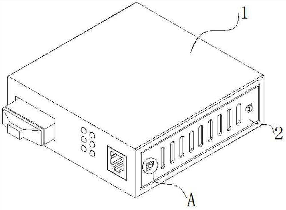
[0031] Such as Figure 1 to Figure 6 As shown, an arc-shaped plate reciprocating push type optical module cooling device provided by the embodiment of the present invention includes an optical module transceiver 1, a heat dissipation plate 2 is arranged on the front side of the optical module transceiver 1, and a heat dissipation plate 2 is arranged on the rear side of the heat dissipation plate 2. There is a reciprocating heat dissipation structure 3, the right side inside the reciprocating heat dissipation structure 3 is fixedly connected with a reset mechanism 4, the surface of the reset mechanism 4 is used in conjunction w...
PUM
Abstract
The invention discloses an arc-shaped plate reciprocating pushing type optical module heat dissipation device which comprises an optical module transceiver, a heat dissipation plate is arranged on the front side of the optical module transceiver, and a reciprocating heat dissipation structure is arranged on the rear side of the heat dissipation plate. According to the invention, through cooperative use of the optical module transceiver, the heat dissipation plate, the reciprocating heat dissipation structure, a heat dissipation frame, a sliding rod, a first limiting block, a first fixing plate, a fixing column, a turntable, a motor, an arc-shaped heat dissipation group, a reset mechanism, a second fixing plate, a first limiting shell, a second limiting block, a fixing rod, a limiting mechanism, a second limiting shell, a third limiting block, a fourth limiting block, a clamping rod, a flexible block and a clamping block, the problem that a large amount of hot air is accumulated in the optical module and the photoelectric conversion efficiency of the optical module becomes low due to the fact that an existing optical module generates too much heat in the use process and a heat dissipation opening cannot well replace air inside equipment with air outside the equipment is solved.
Description
technical field [0001] The invention belongs to the technical field of optical module heat dissipation, and in particular relates to a reciprocating pushing type optical module heat dissipation device of an arc-shaped plate. Background technique [0002] The optical module is composed of optoelectronic devices, functional circuits and optical interfaces. The optoelectronic devices include two parts: transmitting and receiving. Simply put, the function of the optical module is photoelectric conversion. The transmitting end converts electrical signals into optical signals. After transmission through optical fibers, receiving The optical signal is then converted into an electrical signal. [0003] Photoelectric conversion requires the use of optical modules, which need to be dissipated during use to improve efficiency. The problem in the existing technology is: the optical module generates too much heat during use, and the heat dissipation port does not work well. The air insi...
Claims
Application Information
Patent Timeline
Application Date:The date an application was filed.
Publication Date:The date a patent or application was officially published.
First Publication Date:The earliest publication date of a patent with the same application number.
Issue Date:Publication date of the patent grant document.
PCT Entry Date:The Entry date of PCT National Phase.
Estimated Expiry Date:The statutory expiry date of a patent right according to the Patent Law, and it is the longest term of protection that the patent right can achieve without the termination of the patent right due to other reasons(Term extension factor has been taken into account ).
Invalid Date:Actual expiry date is based on effective date or publication date of legal transaction data of invalid patent.