
Patch radiation unit and array antenna

A technology of radiating elements and radiating elements, applied in the structural form of radiating elements, antennas, antenna arrays, etc., can solve the problems of high cost of radiating elements and low cross-polarization, and achieve increased bandwidth, increased cross-polarization ratio, and cross-polarization The effect of high ratio

Active Publication Date: 2021-09-24
WUHAN HONGXIN TELECOMM TECH CO LTD
View PDF7 Cites 0 Cited by
  • Summary
  • Abstract
  • Description
  • Claims
  • Application Information

AI Technical Summary

Problems solved by technology

[0004] The invention provides a patch radiation unit and an array antenna, which are used to solve the defects of high cost of the radiation unit and low cross-polarization ratio in the prior art

Method used


Image

  • Patch radiation unit and array antenna
  • Patch radiation unit and array antenna
  • Patch radiation unit and array antenna

Examples


Embodiment Construction

[0034] In order to make the purpose, technical solutions and advantages of the present invention clearer, the technical solutions in the present invention will be clearly and completely described below in conjunction with the accompanying drawings in the present invention. Obviously, the described embodiments are part of the embodiments of the present invention , but not all examples. Based on the embodiments of the present invention, all other embodiments obtained by persons of ordinary skill in the art without creative efforts fall within the protection scope of the present invention.

[0035] In the description of the present invention, it should be noted that unless otherwise specified and limited, the terms "installation", "connection" and "connection" should be understood in a broad sense, for example, it can be a fixed connection or a detachable connection. Connected, or integrally connected; it can be mechanically connected or electrically connected; it can be directly...


PUM


Abstract

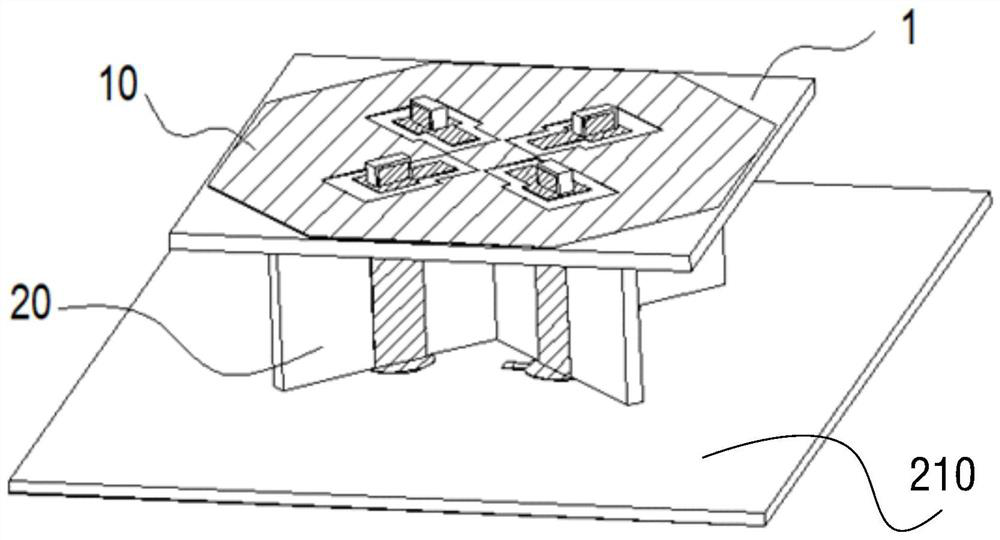
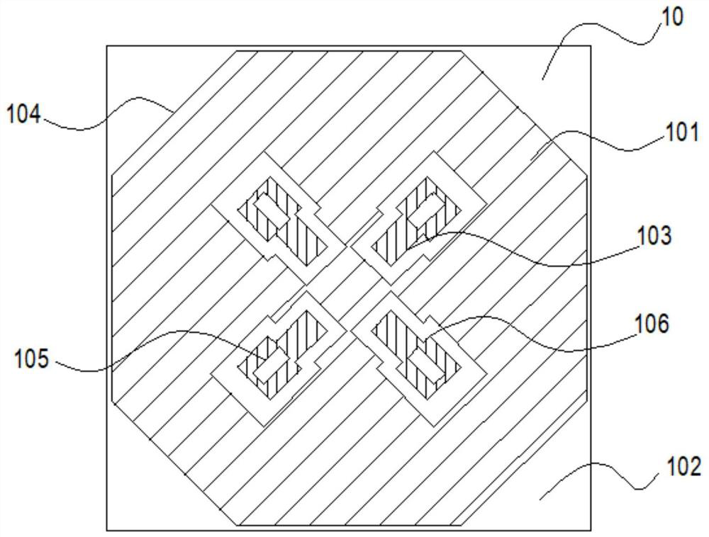
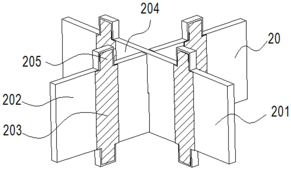
The invention provides a patch radiation unit and an array antenna. The patch radiation unit comprises a radiation element, a feed element and a microstrip bonding pad. The feed element and the radiation element are connected in an inserting manner and are welded and fixed through respective bonding pads; and the feed element is arranged right below the radiation element and is mounted on the microstrip bonding pad. According to the patch radiation unit provided by the invention, the characteristics of low profile, enough wide bandwidth and high cross polarization ratio are realized, resonance is formed by adding inductive and capacitive structures to improve the working bandwidth of the radiation unit, the working bandwidth of the radiation unit is expanded to 3300-3800MHz, and the cross polarization ratio is improved by using four-side chamfers.

Description

technical field [0001] The invention relates to the technical field of antennas, in particular to a patch radiation unit and an array antenna. Background technique [0002] As the requirements for communication in life are getting higher and higher, higher speed and more massive data exchange are required, which leads to the development and change of communication. Today, the 5G era and the trial commercial deployment of 5G networks have ushered in, marking that the integration of base station main equipment and large-scale array antennas will inevitably become a 5G communication trend. The demand for massive MIMO antennas will be much greater than traditional antennas. At the same time, the demand for 5G The portability and low cost requirements of the antenna are getting higher and higher. [0003] However, large-scale antenna arrays in the 5G era have higher requirements for the radiation unit, including increasing the working frequency band for transmitting information,...

Claims


Application Information

Patent Timeline
Patent Type & Authority Applications(China)
IPC IPC(8): H01Q1/38H01Q1/50H01Q15/24H01Q21/00
CPCH01Q1/38H01Q1/50H01Q15/24H01Q21/0006
Inventor 李慧敏刘凯婷刘正贵孙小明
Owner WUHAN HONGXIN TELECOMM TECH CO LTD
Learn More