
Scanning control circuit and driving method thereof, shift register and display device

A scanning control and circuit technology, which is applied in the fields of shift registers, scanning control circuits and their drivers, and display devices, can solve the problems of the scanning control circuit being unable to output scanning signals, the influence of transistor stability, and the excessive voltage difference of the transistors. Ensure normal lighting, avoid excessive pressure difference, and improve reliability

Active Publication Date: 2021-09-24
WUHAN TIANMA MICRO ELECTRONICS CO LTD
View PDF5 Cites 2 Cited by
  • Summary
  • Abstract
  • Description
  • Claims
  • Application Information

AI Technical Summary

Problems solved by technology

[0003] However, based on the specific structure of the existing scanning control circuit, in the process of node potential changes, the voltage difference between the two ends of the transistor will be too large, which will affect the stability of the transistor, and in severe cases will affect the The working state of the entire scanning control circuit, which in turn causes the scanning control circuit to fail to output correct scanning signals

Method used


Image

  • Scanning control circuit and driving method thereof, shift register and display device
  • Scanning control circuit and driving method thereof, shift register and display device
  • Scanning control circuit and driving method thereof, shift register and display device

Examples


Embodiment Construction

[0038] In order to better understand the technical solutions of the present invention, the embodiments of the present invention will be described in detail below in conjunction with the accompanying drawings.

[0039] It should be clear that the described embodiments are only some of the embodiments of the present invention, not all of them. Based on the embodiments of the present invention, all other embodiments obtained by persons of ordinary skill in the art without creative efforts fall within the protection scope of the present invention.

[0040] Terms used in the embodiments of the present invention are only for the purpose of describing specific embodiments, and are not intended to limit the present invention. As used in the embodiments of the present invention and the appended claims, the singular forms "a", "said" and "the" are also intended to include the plural forms unless the context clearly indicates otherwise.

[0041]It should be understood that the term "and...


PUM


Abstract

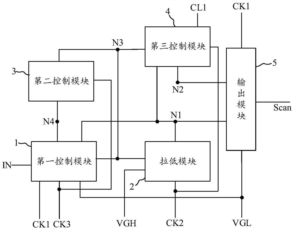
The embodiment of the invention provides a scanning control circuit and a driving method thereof, a shift register and a display device, relates to the technical field of display, and aims to improve the circuit stability. The scan control circuit includes: a first control module that transmits voltages to a first node and a fourth node in response to a voltage of a first clock signal and a voltage of a third clock signal, and transmits voltages to a third node in response to the third clock signal; a pull-down module which responds to the voltage of the third node and the voltage of the first node and transmits the voltage to the first node; a second control module which responds to the voltage of the fourth node and transmits the voltage to the third node; a third control module which responds to the voltage of the third node, the voltage of the second clock signal and the voltage of the first node and transmits the voltage to the second node; and an output module which responds to the voltage of the first node and the voltage of the second node and outputs a scanning signal to the grid line.

Description

【Technical field】 [0001] The invention relates to the field of display technology, in particular to a scanning control circuit and its driving method, a shift register and a display device. 【Background technique】 [0002] The display device is provided with a plurality of cascaded scanning control circuits, and the scanning control circuits are used to output scanning signals to the gate lines to drive the display panel to display images normally. It can be understood that the scan control circuit is composed of multiple transistors and multiple nodes. During the operation of the scan control circuit, the potential of each node will change, thus causing the voltage difference across the transistor to change accordingly. [0003] However, based on the specific structure of the existing scanning control circuit, in the process of node potential change, the voltage difference between the two ends of the transistor will be too large, which will affect the stability of the transi...

Claims


Application Information

Patent Timeline
Patent Type & Authority Applications(China)
IPC IPC(8): G09G3/3266G09G3/3258G11C19/28
CPCG09G3/3266G09G3/3258G11C19/28G09G2310/0286
Inventor 张蒙蒙周星耀李玥杨帅
Owner WUHAN TIANMA MICRO ELECTRONICS CO LTD
Learn More