


Quick Research
Generate reliable direction feasibility study reports for your R&D in just a few steps.

Technical Q&A
Discover and master advanced knowledge NOW. Basics, ideas, possibilities, all at once.

Find Solutions
As an expert in R&D theories, this can generate solutions to your technical problems instantly.

Evaluate Feasibility
Analyze your overall solution with one click, know your potential R&D risks in advance.

Monitor Landscape
Get weekly tech updates, stay abreast of the latest tech innovations and key insights.
Wireless salinity sensing system based on evaporation-induced power generation battery
An evaporation-induced, salinity sensing technology, applied in the field of wireless salinity sensing system design, can solve the problems of low energy conversion efficiency, low output power, limitations, etc., and achieves low equipment requirements, simple preparation process, and structure. less restricted effect
- Summary
- Abstract
- Description
- Claims
- Application Information
AI Technical Summary
Problems solved by technology
Method used
Image

Examples
Embodiment 1
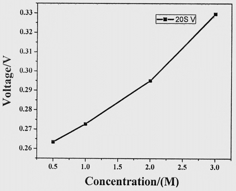
[0032] Example 1 Experiment on the relationship between sensing voltage and salinity gradient, the specific process is as follows:
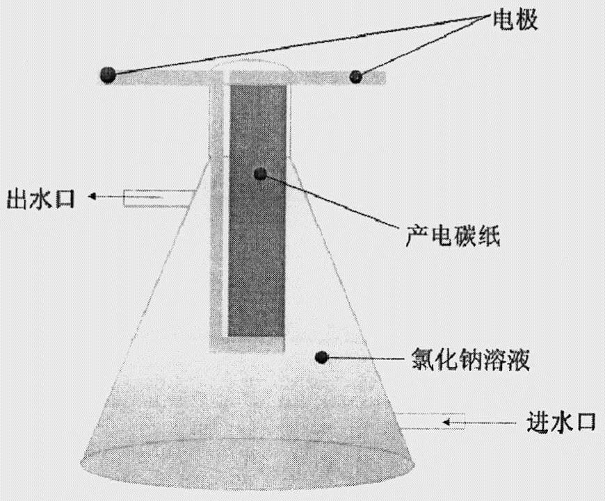
[0033] First configure the NaCl solution (0.5mol / L, 1mol / L, 2mol / L, 3mol / L) with the amount of gradient substance, fix the built power generation functional area in a 50mL conical triangular beaker with upper and lower mouths, and set the power generation function The silver wire at the dry end of the area is connected to the working electrode of the electrochemical workstation, and the silver wire at the wet end of the power generation functional area is connected to the reference electrode of the electrochemical workstation. Through the peristaltic pump, different concentrations of NaCl solutions are sequentially passed into the main system of evaporation-induced power generation constructed above, and the relationship between the voltage and the concentration of the influent NaCl solution is recorded by the electrochemical workstation (take the...
Embodiment 2
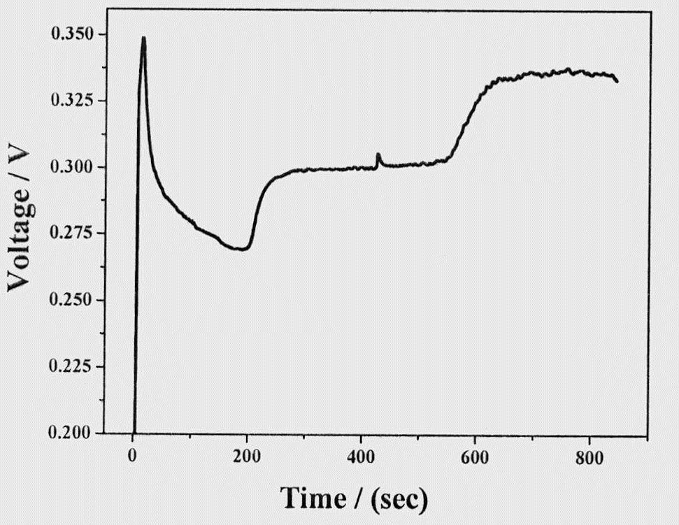
[0034] Embodiment 2 The specific operation process of the salinity sensing system is as follows:
[0035] First, connect the silver wire at the dry end of the power generation function area to the A0 port of Arduino, connect the silver wire at the wet end to the GND port of Arduino, and inject 0.5mol / L NaCl solution into a 50mL conical triangular beaker with upper and lower openings through a peristaltic pump , when the battery power production is stable, that is, when the voltage reaches 0.2634V, 1mol / L NaCl solution is introduced, and the salinity of the water in the system will be replaced after 120s, and the voltage will change (the corresponding voltage of 1mol / L NaCl solution is 0.2727V, The corresponding voltage of 2mol / L NaCl solution is 0.2951V), when the concentration of water in the system is 1-2mol / L, the LED light is on, when the concentration of water in the system is greater than 3mol / L, that is, when the voltage is 0.3296V, the buzzer will sound The device soun...
PUM
 Abstract
Description
Claims
Application Information
 - R&D Engineer
- R&D Manager
- IP Professional
- Industry Leading Data Capabilities
- Powerful AI technology
- Patent DNA Extraction
Browse by: Latest US Patents, China's latest patents, Technical Efficacy Thesaurus, Application Domain, Technology Topic, Popular Technical Reports.
© 2024 PatSnap. All rights reserved.Legal|Privacy policy|Modern Slavery Act Transparency Statement|Sitemap|About US| Contact US: help@patsnap.com