One-way transmission gear structure
A technology of gear structure and one-way transmission, which is applied to the transmission device, one-way clutch, transmission device parts, etc., can solve the problem of high cost of one-way transmission gear structure, and achieve the advantages of easy promotion and use, convenient use and low use cost Effect
- Summary
- Abstract
- Description
- Claims
- Application Information
AI Technical Summary
Problems solved by technology
Method used
Image

Examples
Embodiment 1
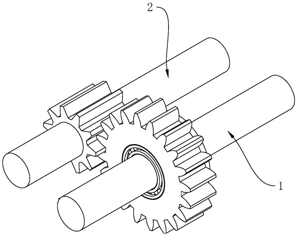
[0068] refer to figure 1 , the one-way transmission gear structure includes a driving gear 1 for connecting the motor and a driven gear 2 for connecting the movable parts. 1 Input the torque, and then transmit the torque to the driven gear 2 through the driving gear 1, so that the driven gear 2 can drive the movable parts to do work.
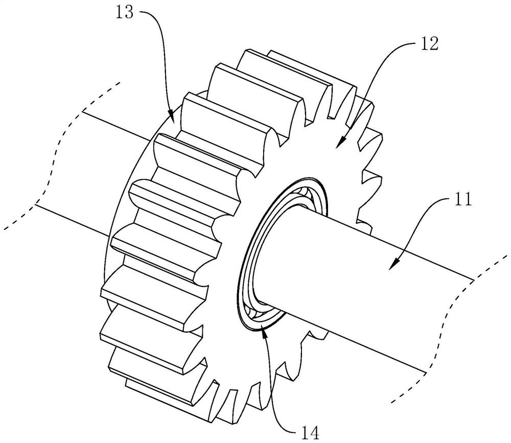
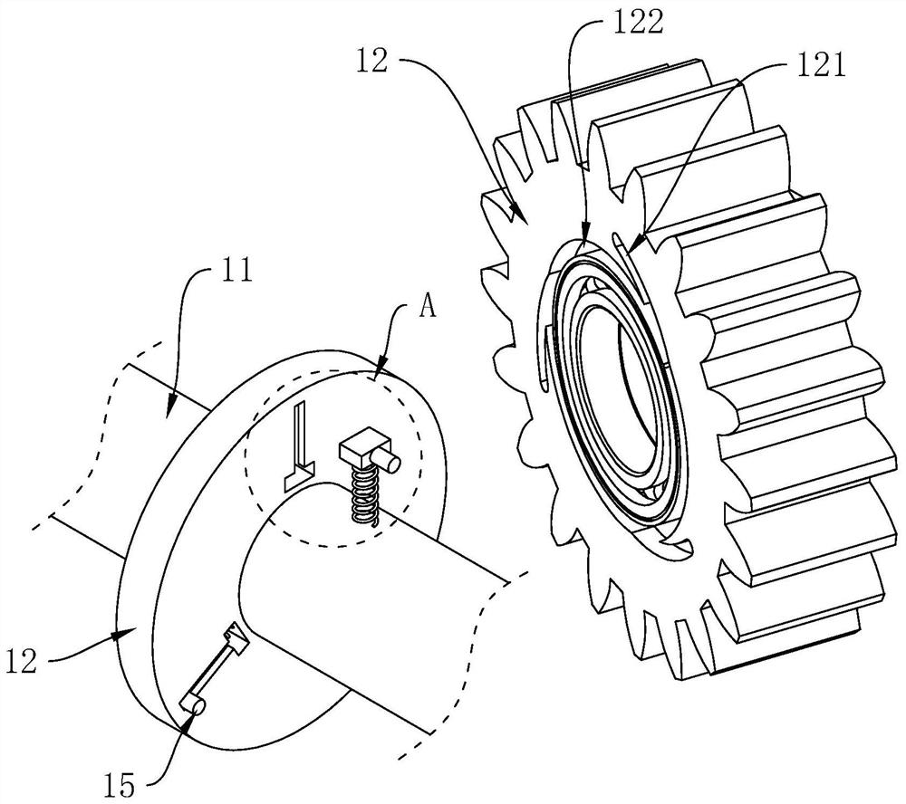
[0069] refer to figure 2 with image 3 , the driving gear 1 includes a transmission shaft 11, a gear body 12 and a limiting wheel 13, the transmission shaft 11 is used to connect the motor to input torque, the gear body 12 is sleeved on the transmission shaft 11 and is rotationally connected with the transmission shaft 11 to limit the The position wheel 13 and the drive shaft 11 are relatively fixed in the circumferential direction; wherein, a linkage assembly 15 is arranged between the limit wheel 13 and the gear body 12, and the linkage assembly 15 is used to make the drive shaft 11 perform forward rotation and reverse rotation , the gear ...
Embodiment 2
[0082] Refer to Push 6 and Figure 7 The difference between this embodiment and Embodiment 1 is that the lead-out structure 122 is set as a guide slope 124, and the guide slope 124 is arranged in one end of the limit groove 121 close to the gear body 12, and the two sides of the guide slope 124 are connected with the limit groove respectively. The two sides of 121 are connected, the slope bottom of guide slope 124 is connected with the bottom surface of limit groove 121 , and the slope top of guide slope 124 is connected with a side of gear body 12 close to limit wheel 13 .
[0083] refer to Figure 8 , the limiting wheel 13 is fixedly connected to the transmission shaft 11, the limiting rod 151 includes a sliding part 155, a telescopic part 156 and a second elastic member 157, and the end of the sliding part 155 away from the gear body 12 is connected to the sliding slot 131, And an insertion hole 158 is provided in the end of the sliding part 155 close to the gear body 12, ...
Embodiment 3
[0086] Referring to Push 9, the difference between this embodiment and Embodiment 1 is that the lead-out structure 122 includes a guide slope 124, and the guide slope 124 is arranged in one end of the limit groove 121 close to the gear body 12, and the two sides of the guide slope 124 are respectively connected with the limit The two sides of the positioning groove 121 are connected, the bottom of the guiding slope 124 is connected to the bottom of the limiting groove 121 , and the top of the guiding slope 124 is connected to a side of the gear body 12 close to the limiting wheel 13 .
[0087] refer to Figure 9 with Figure 10On the outer wall of the transmission shaft 11, a spline 111 is arranged around the axis of the transmission shaft 11, and a keyway 135 is provided on the inner wall of the limit wheel 13 to engage with the spline 111. Through the keyway 135 and The cooperation between the splines 111 makes the limit wheel 13 only able to move back and forth along the l...
PUM
 Abstract
Description
Claims
Application Information
 - R&D
- Intellectual Property
- Life Sciences
- Materials
- Tech Scout
- Unparalleled Data Quality
- Higher Quality Content
- 60% Fewer Hallucinations
Browse by: Latest US Patents, China's latest patents, Technical Efficacy Thesaurus, Application Domain, Technology Topic, Popular Technical Reports.
© 2025 PatSnap. All rights reserved.Legal|Privacy policy|Modern Slavery Act Transparency Statement|Sitemap|About US| Contact US: help@patsnap.com