A cutting machine with high conveying efficiency

A technology of conveying efficiency and cutting machine, which is applied in metal processing and other directions, can solve the problems of low adaptability and the inability of the conveyor belt to convey workpieces in an orderly manner, and achieve the effect of improving adaptability and improving conveying efficiency

Active Publication Date: 2021-11-19
江苏德励达新材料股份有限公司
View PDF1 Cites 0 Cited by
  • Summary
  • Abstract
  • Description
  • Claims
  • Application Information

AI Technical Summary

Problems solved by technology

[0004] The purpose of the present invention is to provide a cutting machine with high conveying efficiency to solve the technical problem that the conveyor belt cannot convey workpieces in an orderly manner and has low adaptability in the prior art

Method used


Image

  • A cutting machine with high conveying efficiency
  • A cutting machine with high conveying efficiency
  • A cutting machine with high conveying efficiency

Examples


Embodiment Construction

[0066] The present invention is described in further detail now in conjunction with accompanying drawing. These drawings are all simplified schematic diagrams, and only illustrate the basic structure of the present invention in a schematic manner, so they only show the configurations related to the present invention.

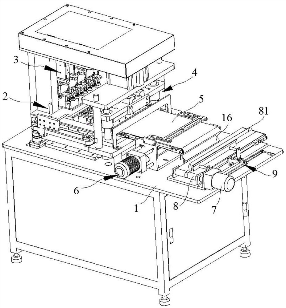
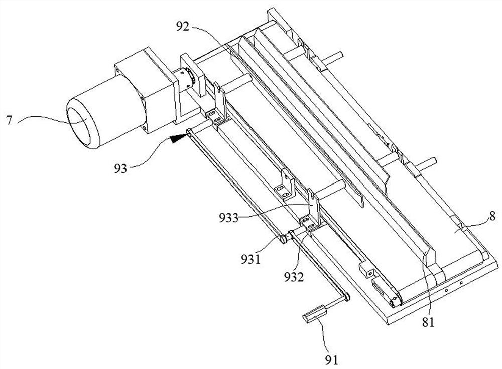
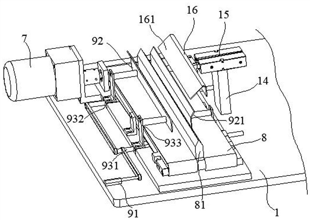
[0067] Such as Figure 1 to Figure 18 As shown, a cutting machine with high conveying efficiency of the present invention includes: a working platform 1, a conveying motor 7, a first conveying belt 8 and an adjusting device 9, and the conveying motor 7 and the first conveying belt 8 are both Fixed on the working platform 1, the working platform 1 is used as the main support and workbench of the cutting machine of the present invention, and the conveying motor 7 is arranged on one side of the first conveyor belt 8; the conveying motor 7 As the main power source of the first conveyor belt 8, it can drive the first conveyor belt 8 to move; the adjustment device 9 ...


PUM


Abstract

The invention relates to a cutting machine with high conveying efficiency, comprising: a working platform, a conveying motor, a first conveying belt and an adjustment device, the conveying motor and the first conveying belt are fixed on the working platform, and the The conveying motor is arranged on one side of the first conveyor belt; the adjustment device is fixed on the working platform, and one end of the adjustment device is arranged above the first conveyor belt; When a conveyor belt is used, adjusting the adjusting device can adapt to the thickness of the plate; the adjustment device can adjust the distance between the two adjusting plates to adapt to plates of different thicknesses, which improves the adaptability of the present invention; at the same time, it can make the plate It can move on the first conveyor belt in an orderly manner, which greatly improves the conveying efficiency of the first conveyor belt.

Description

technical field [0001] The invention relates to the technical field of cutting machines, in particular to a cutting machine with high conveying efficiency. Background technique [0002] Application number: CN201120269593.3, publication (announcement) number: CN202185947U, floating conveyor belt cutting machine, floating conveyor belt cutting machine, including cutting machine, belt conveyor mechanism, floating mechanism, floating mechanism is fixed on the cutting machine On the fuselage of the cutting machine, the conveyor belt is between the upper template and the workbench of the cutting machine, and the frame of the belt conveying mechanism is connected with the output end of the floating mechanism. The slide rail on the body of the cutting machine slides up and down when cutting. When cutting, the conveyor belt is in the groove of the cutting machine table, which will not produce too deep cut marks, which prolongs the service life of the conveyor belt. The conveyor belt ...

Claims


Application Information

Patent Timeline
Patent Type & Authority Patents(China)
IPC IPC(8): B26D1/08B26D7/06B26D7/20B26D7/18B26D5/12B26D7/01
CPCB26D1/08B26D7/0625B26D7/20B26D7/1854B26D5/12B26D7/015B26D2007/0018
Inventor 顾斌王华
Owner 江苏德励达新材料股份有限公司
Why Eureka
Try Eureka