
Welding machining process for steel-structure stand column prefabricated part

A processing technology and prefabricated part technology, which is applied in the field of steel structure column prefabricated welding processing technology, can solve the problems of lower rib plate use value, longer production time of column prefabricated parts, large risks, etc., to improve quality, improve production efficiency, The effect of ensuring stability

Inactive Publication Date: 2021-09-24
武汉诺意鑫装饰工程有限公司
View PDF0 Cites 0 Cited by
  • Summary
  • Abstract
  • Description
  • Claims
  • Application Information

AI Technical Summary

Problems solved by technology

[0004] ①When the existing welding equipment welds the column and the rib, the position adjustment between the column and the rib is manually adjusted, and the column is large, which will bring greater labor intensity to the workers, and the manual It is difficult to align the installation position between the column and the rib, which will easily lead to a decrease in the use value of the rib, and there will also be a greater risk of the prefabricated parts during use
[0005] ②When the existing welding equipment welds the column and the rib, due to the large size of the column, the column cannot be clamped and rotated well, so that the welding process between each rib and the column takes a long time It takes more time to adjust the position of the column, which leads to longer production time of the column prefab

Method used


Image

  • Welding machining process for steel-structure stand column prefabricated part
  • Welding machining process for steel-structure stand column prefabricated part
  • Welding machining process for steel-structure stand column prefabricated part

Examples


Embodiment Construction

[0033] In order to make the technical means realized by the present invention, creative features, goals and effects easy to understand, the following combination Figure 1 to Figure 8 , to further elaborate the present invention.

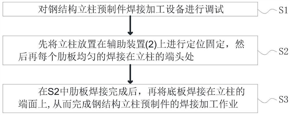
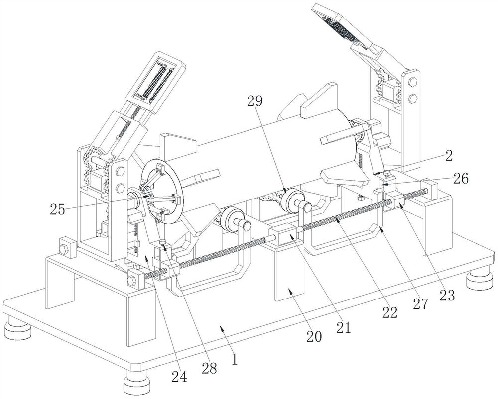
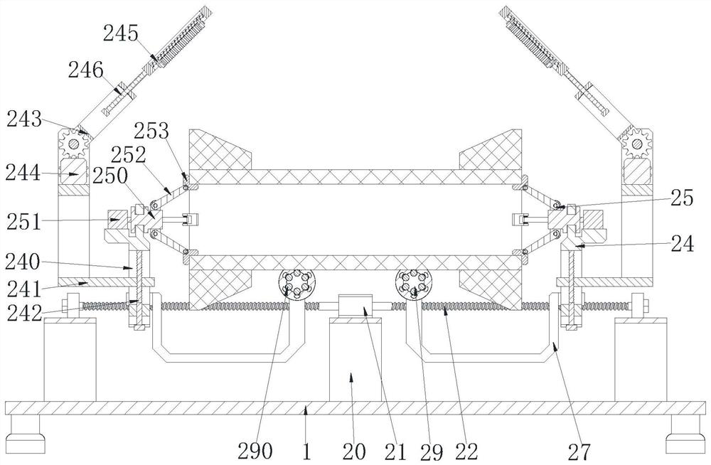
[0034] A steel structure column prefabricated welding process, which uses a steel structure column prefabricated welding processing equipment, the steel structure column prefabricated welding processing equipment includes a base 1 and an auxiliary device 2, using the above steel structure column prefabricated welding When the processing equipment welds the prefabricated steel structure column, the specific method is as follows:

[0035] S1. Preparatory work: debug the welding processing equipment for the prefabricated steel structure column.

[0036] S2. Welding process of the rib plate at the end of the column: ①In the initial state, the auxiliary wire block 23 is at the end of the auxiliary screw 22, and then the auxiliary motor 21 is started acc...


PUM


Abstract

The invention relates to a welding machining process for a steel-structure stand column prefabricated part. In the welding machining process for the steel-structure stand column prefabricated part, welding machining equipment for the steel-structure stand column prefabricated part is used, and comprises a base and an auxiliary device, wherein the auxiliary device is arranged on the upper surface of the base. According to the invention, the problems that when existing welding equipment is used for welding a stand column and rib plates, the positions between the stand column and the rib plates are manually adjusted, the stand column is large in size, large labor intensity is brought to workers, the installation positions of the stand column and the rib plates are difficult to align manually, and then the use value of the rib plates is easily reduced; and due to the fact that the stand column is large in size, the stand column cannot be well clamped and rotated, and welding machining between each rib plate and the stand column needs a long time to adjust the position of the stand column, so that the manufacturing time for the stand column prefabricated part is prolonged.

Description

technical field [0001] The invention relates to the field of steel structure manufacturing, in particular to a welding process for prefabricated steel structure columns. Background technique [0002] As the name suggests, the prefabricated steel structure column is different from the concrete column. It uses steel pipe, H-shaped steel or box-shaped steel to replace the concrete column. It has the characteristics of light weight, small cross-section, simple construction and short construction period. The column prefabricated parts welded together by ribs, ribs and bottom plates. [0003] At present, the following problems exist in the welding process of prefabricated steel structure columns: [0004] ①When the existing welding equipment welds the column and the rib, the position adjustment between the column and the rib is manually adjusted, and the column is large, which will bring greater labor intensity to the workers, and the manual It is difficult to align the installa...

Claims


Application Information

Patent Timeline
Patent Type & Authority Applications(China)
IPC IPC(8): B23K31/02B23K37/04B23K37/053
CPCB23K31/02B23K37/0443B23K37/053
Inventor 宋锦来
Owner 武汉诺意鑫装饰工程有限公司
Learn More