Power distribution cabinet profile cutting equipment with impact deformation prevention function
A technology for cutting equipment and cabinet profiles, which is applied in the field of power distribution cabinet profile cutting equipment, which can solve the problems of impact deformation of profiles and inability to accurately cut parts that vibrate, and achieve the effect of reducing vibration
- Summary
- Abstract
- Description
- Claims
- Application Information
AI Technical Summary
Problems solved by technology
Method used
Image
Examples
Embodiment 1
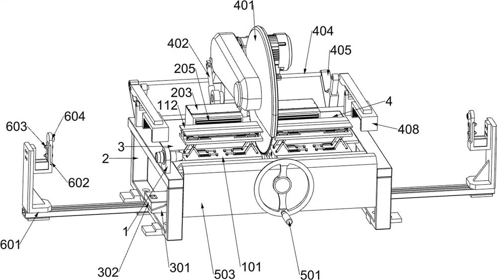
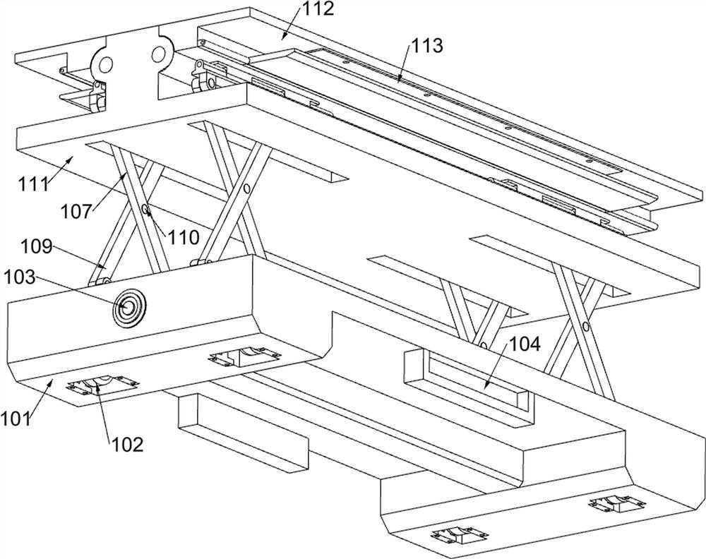
[0036] A profile cutting equipment for power distribution cabinets with anti-shock deformation, according to figure 1 and figure 2 As shown, it includes a main support assembly, an auxiliary support assembly, a filling assembly, a cutting assembly, a section scanner 1, a main support 2, a left top plate 3, a right top plate 4 and an internal support 5; Bracket 2; the left top plate 3 is fixedly connected to the upper left side of the rear side of the main bracket 2; the right top plate 4 is fixedly connected to the upper right side of the rear side of the main bracket 2; A set of main support components are placed on the left and right sides of the surface; a set of auxiliary support components are respectively fixed on the lower surfaces of the left top plate 3 and the right top plate 4; two sets of filling components are fixed below the main support 2; There are cutting components.
[0037]The section scanner 1 scans the section of the profile to be cut, and independently...
Embodiment 2
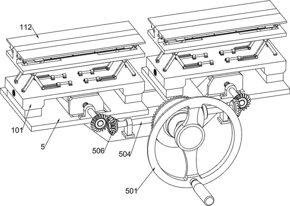
[0050] On the basis of Example 1, according to figure 1 and Figure 11 As shown, a clamping assembly is also included. The internal bracket 5 is provided with a clamping assembly. The clamping assembly includes a runner 501, a first bevel gear 502, a baffle 503, a first rotating shaft 504, a second bevel gear 505, The 3rd bevel gear 506, the double-thread screw mandrel 507, the 4th bevel gear 508, the front fixing plate 509, the front clamping block 510, the rear fixing plate 511 and the rear clamping block 512; The rear end of the runner 501 is fixedly connected with a first bevel gear 502; the rear side of the runner 501 is rotatably connected with a baffle 503; the baffle 503 is affixed to the main bracket 2; A rotating shaft 504; the middle part of the outer surface of the first rotating shaft 504 is affixed with a second bevel gear 505; the first bevel gear 502 meshes with the second bevel gear 505; the left and right sides of the outer surface of the first rotating shaf...
Embodiment 3
[0055] On the basis of Example 1, according to figure 1 As shown, an auxiliary positioning assembly is also included. A group of auxiliary positioning assemblies are fixedly connected to the left and right sides of the main bracket 2. The auxiliary positioning assembly includes an external bracket 601, an adjusting piece 602, a locking bolt 603 and an infrared emitter 604; A set of external brackets 601 are fixedly connected to the left and right sides of the bracket 2 through slide rails; an adjusting piece 602 is arranged on the inner top of the external bracket 601; two sets of locking bolts 603 are connected between the adjacent external brackets 601 and the adjusting piece 602 ; An infrared emitter 604 is affixed to the inner top of the adjustment piece 602 .
[0056] In order to speed up the positioning of the two sets of main support components, the adjustment plate 602 is adjusted by the locking bolt 603 to drive and the infrared transmitter 604 is aligned with the inf...
PUM
 Abstract
Description
Claims
Application Information
 - R&D
- Intellectual Property
- Life Sciences
- Materials
- Tech Scout
- Unparalleled Data Quality
- Higher Quality Content
- 60% Fewer Hallucinations
Browse by: Latest US Patents, China's latest patents, Technical Efficacy Thesaurus, Application Domain, Technology Topic, Popular Technical Reports.
© 2025 PatSnap. All rights reserved.Legal|Privacy policy|Modern Slavery Act Transparency Statement|Sitemap|About US| Contact US: help@patsnap.com


