Gas network and method for detecting leaks in a gas network under pressure or under vacuum

A gas and network technology, applied in fluid pressure actuation devices, fluid pressure actuation system safety, gas/liquid distribution and storage, etc., can solve problems such as pipeline network leakage is not allowed

Pending Publication Date: 2021-09-17
ATLAS COPCO AIRPOWER NV
View PDF2 Cites 0 Cited by
  • Summary
  • Abstract
  • Description
  • Claims
  • Application Information

AI Technical Summary

Problems solved by technology

[0008] The disadvantage of such known methods is that they do not allow the detection of leaks in complex piping networks between source and consumer or consumer areas
Additionally, gas distribution networks or vacuum networks are sources of leaks that cannot be underestimated

Method used


Image

  • Gas network and method for detecting leaks in a gas network under pressure or under vacuum
  • Gas network and method for detecting leaks in a gas network under pressure or under vacuum

Examples


Embodiment Construction

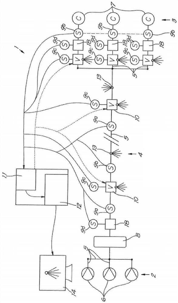
[0059] figure 1 The gas network 1 in mainly comprises a source side 2, a consumer side 3 and a network 4 of pipes 5 in between.

[0060] In this case, the gas network 1 is a gas network 1 under pressure. The gas may be air, oxygen or nitrogen or any other non-toxic and / or harmful gas or gas mixture.

[0061] The source side 2 comprises a number of compressors 6, in this case three, which generate compressed air. The consumer side 3 includes a plurality of compressed air consumers 7 , in this case also three.

[0062] It is also possible that the compressor 6 contains a compressed air dryer.

[0063] It is not excluded that there may also be a compressor 6 downstream of the gas network 1 . This is called a "booster compressor".

[0064] Compressed air is conveyed from the compressor 6 to the consumer 7 via a network 4 of pipes 5 . This network 4 is in most cases a very complex network of pipes 5 .

[0065] figure 1 This network 4 is shown in a very schematic and simplifie...


PUM


Abstract

Method, for detecting and quantifying leaks {13} in a gas network (1) under pressure or vacuum, the gas network (1) comprising: - one or more sources (6) of compressed gas or vacuum; - one or more consumers (7) or consumer areas of compressed gas or vacuum applications; - pipelines or a network of pipelines (5) to transport the gas or vacuum from the sources (6) to the consumers (7), consumer areas or applications; - a plurality of sensors (9a, 9b) which determine one or a plurality of physical parameters of the gas at different times and.locations in the gas network (1); characterized in that the gas network (1) is further provided with a number of controllable or adjustable relief valves (10) and that the method comprises the following steps: - a training phase (16) in which a mathematical model is established between the measurements of a first group of sensors (9a, 9b) and a second group of sensors (9a, 9b), based on different measurements of these sensors (9a, 9b) in which the adjustable relief valves (10) are controlled in a predetermined order and according to well-designed scenarios to generate leaks (13); - an operational phase (17), in which the mathematical model established between the measurements of the first group of sensors (9a, 9b) and the second group of sensors (9a, 9b) is used to detect, locate and quantify leaks (13) in the gas network (1); wherein the operational phase (17) comprises the following steps: - controlling the relief valves in a predetermined order and according to 'well-designed scenarios; - reading out the first group of sensors (9a, 9b); based on these readout measurements, calculating or determining the value of the second group of sensors (9a, 9b) with the help of the mathematical model; - comparing the calculated or determined values of the second group of sensors (9a, 9b) with the read values of the second group of sensors (9a, 9b) and determining the difference between them; - determining whether there is a leak (13) in the gas network (1) on the basis of the aforementioned difference and any of its derivatives; and - generating an alarm and/or generating a leakage rate if a leak (13) is detected.

Description

technical field [0001] The invention relates to a method for detecting leaks in a gas network under pressure or under vacuum. [0002] More specifically, the invention aims to be able to detect and quantify leaks occurring in gas networks. Background technique [0003] "Gas" here means, for example, air, but not necessarily. [0004] Methods for monitoring or controlling gas networks under pressure are known and are therefore established for long, straight pipes in which the inflow flow is not constant due to the compressibility of the gas in question. Must be equal to the outgoing flow. [0005] These methods are based on many assumptions, such as very long pipes, straight pipes, which are not suitable for complex gas networks under pressure, where one or more compressor devices supply gas under pressure to a complex network of consumers. [0006] Furthermore, methods are already in place, as described in US 7.031.850 B2 and US 6.711.507 B2, to detect leaks in the pneuma...

Claims


Application Information

Patent Timeline
Patent Type & Authority Applications(China)
IPC IPC(8): G01M3/28F15B19/00F17D5/02F17D5/06
CPCG01M3/2815F17D5/02F17D5/06F15B19/005F15B2211/8855F15B20/005F15B2211/50518F15B2211/6309F15B2211/857F15B2211/855F15B2211/6323F15B2211/634F15B2211/89F17D5/005G05B13/0265G05B13/042G05B23/0243G06Q10/20G06Q50/06
Inventor P·戈伊恩斯E·罗劳蒂
Owner ATLAS COPCO AIRPOWER NV
Why Eureka
Try Eureka