


Quick Research
Generate reliable direction feasibility study reports for your R&D in just a few steps.

Technical Q&A
Discover and master advanced knowledge NOW. Basics, ideas, possibilities, all at once.

Find Solutions
As an expert in R&D theories, this can generate solutions to your technical problems instantly.

Evaluate Feasibility
Analyze your overall solution with one click, know your potential R&D risks in advance.

Monitor Landscape
Get weekly tech updates, stay abreast of the latest tech innovations and key insights.
Mobile terminal
A mobile terminal and vibrator technology, applied in the direction of telephone structure, sensor, branch equipment, etc., can solve the problems of insufficient driving force of vibrator, increased impedance, insufficient high-frequency volume of mobile phone, etc.
- Summary
- Abstract
- Description
- Claims
- Application Information
AI Technical Summary
Problems solved by technology
Method used
Image

Examples
example 1
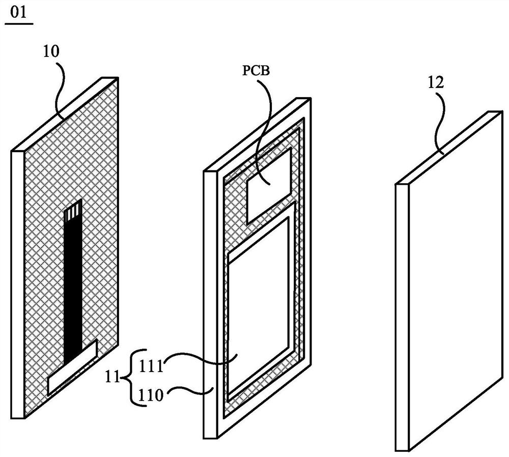
[0061] In this example, when the size of the gap H between the carrier plate 111 of the middle frame 11 and the back surface B of the display module 10 is limited, as Figure 3a As shown, at least a part of the vibrator 20 can be disposed in the accommodation cavity 103 .
[0062] The above-mentioned vibrator 20 may include such as Figure 3a Shown are a first magnet 201 , a second magnet 202 , a coil 200 and at least one third magnet 203 . The first magnet 201 , the coil 200 and the third magnet 203 are all connected to the back surface B of the display module 10 . like Figure 3b As shown, the first magnet 201 may be located in the closed area formed by the wires of the coil 200 . In addition, if Figure 3a As shown, the second magnet 202 is connected to the bearing plate 111 of the middle frame 11 . Moreover, the second magnet 202 is located opposite to the first magnet 201 .
[0063] In addition, in order to connect the first magnet 201, the coil 200 and the third ma...
example 2
[0104] This example is the same as Example 1, such as Figure 3a As shown, at least a part of the vibrator 20 can be disposed in the accommodation cavity 103 . The vibrator 20 includes a first magnet 201 , a second magnet 202 , a coil 200 and at least one third magnet 203 . The first magnet 201 , the coil 200 and the third magnet 203 can be disposed in the first magnetic isolation cover 41 . The third magnet 203 is disposed inside the second magnetic isolation cover 42 . In addition, the vibrator 20 may further include a fourth magnet 204 disposed in the second magnetic isolation cover 42 .
[0105] The difference from Example 1 is that, if Figure 12a As shown, the magnetization direction of the third magnet 203 is parallel to the display surface A of the display module 10 .
[0106] For the convenience of description, in some embodiments of the present application, the Figure 12a The structure shown is taken as an example, and the first pole of the magnet is an N pole,...
PUM
 Abstract
Description
Claims
Application Information
 - R&D Engineer
- R&D Manager
- IP Professional
- Industry Leading Data Capabilities
- Powerful AI technology
- Patent DNA Extraction
Browse by: Latest US Patents, China's latest patents, Technical Efficacy Thesaurus, Application Domain, Technology Topic, Popular Technical Reports.
© 2024 PatSnap. All rights reserved.Legal|Privacy policy|Modern Slavery Act Transparency Statement|Sitemap|About US| Contact US: help@patsnap.com