Intelligent pressure balance control system
A technology of balance control and pressure, applied in fluid pressure control, control/regulation system, electric fluid pressure control, etc. It can solve problems such as difficulty, inability to detect pressure, and inability to improve process level, and achieve easy use and simple structure. , the effect of uniform gas distribution
- Summary
- Abstract
- Description
- Claims
- Application Information
AI Technical Summary
Problems solved by technology
Method used
Image
Examples
Embodiment 1
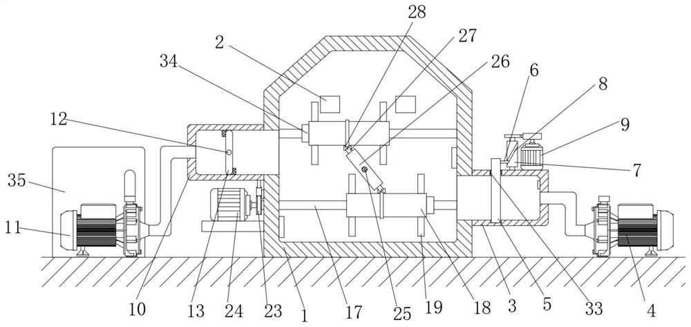
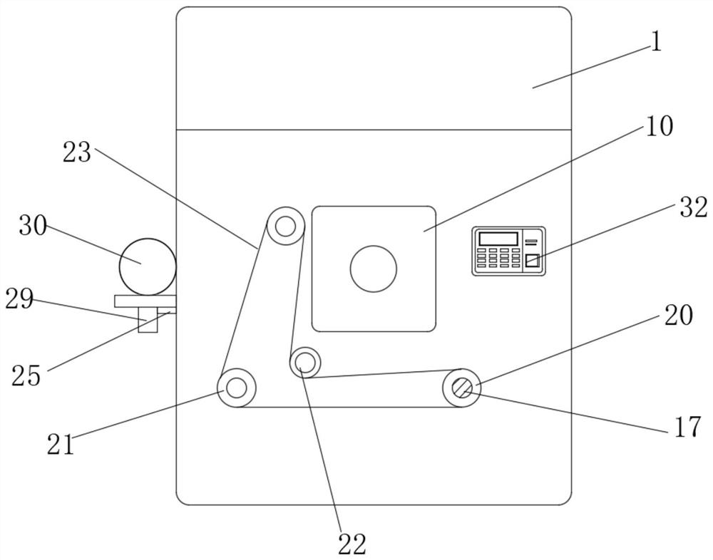
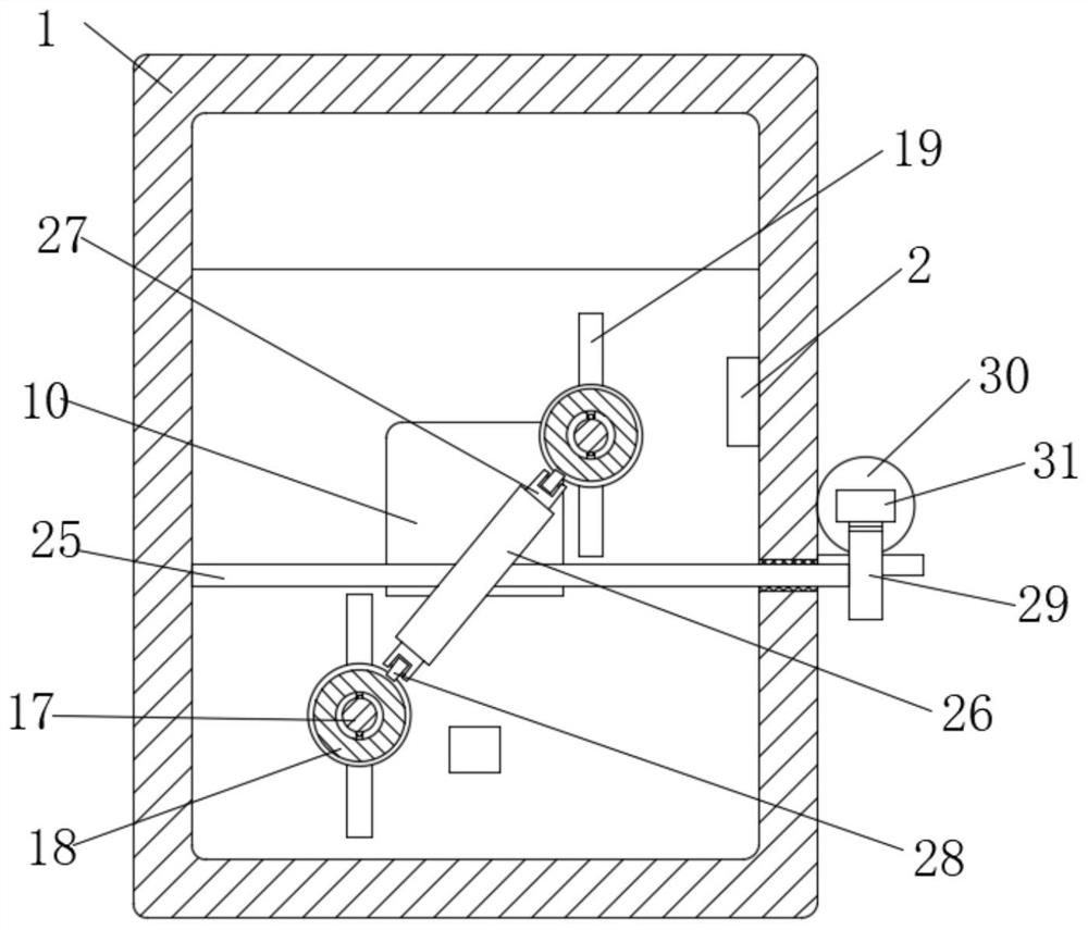
[0029] refer to Figure 1-7 , an intelligent pressure balance control system, including a reaction furnace 1, the inner wall of the reaction furnace 1 is fixedly connected with a plurality of pressure detectors 2, and the two sides of the reaction furnace 1 are respectively fixedly connected with an inlet port 3 and an outlet port 10, and the reaction furnace 1 One side is provided with a pressurizing assembly for increasing the internal pressure of the reactor 1, and the other side of the reactor 1 is provided with a decompression assembly for reducing the internal pressure of the reactor 1, and one side of the reactor 1 is fixedly connected with a control panel 32, The reaction furnace 1 is provided with a stirring assembly for uniform gas distribution in the reaction furnace 1 .
Embodiment 2
[0031]This embodiment is improved on the basis of Embodiment 1: the pressurized assembly includes an air pump 4 arranged on one side of the reaction furnace 1, the outlet pipe of the air pump 4 extends into the air inlet 3, and the air inlet 3 is slidably connected There is a baffle 5, and the top of the baffle 5 slides through the top of the intake end 3, the top of the intake end 3 is connected to the runner 7 in rotation, the outer wall of the runner 7 is provided with a chute 8, and one side of the baffle 5 The top is fixedly connected with the connecting block 6 which is slidingly connected with the chute 8, and the top of the intake end 3 is fixedly connected with the driving motor 9, the output shaft of the driving motor 9 and the runner 7 are driven by gears, and the pressure reducing assembly includes 1 The suction pump 11 on the other side, the suction pipe of the suction pump 11 extends into the air outlet 10, the inside of the air outlet 10 is horizontally rotated a...
Embodiment 3
[0033] This embodiment is improved on the basis of Embodiment 1: the reaction furnace 1 is provided with a gas collection box 35 near the side of the suction pump 11, and the gas outlet pipe of the suction pump 11 extends into the gas collection box 35, and passes through the gas collection box 35 Collect the gas in the reaction furnace 1 to prevent the gas in the reaction furnace 1 from overflowing and polluting the environment.
[0034] Working principle: start the rotating motor 24, and the rotating motor 24 drives the two rotating rods 17 to rotate through the first synchronous wheel 20, the second synchronous wheel 21, the third synchronous wheel 22 and the synchronous belt 23, and then through the rotation of the stirring blade 19, Make the gas in the reaction furnace 1 evenly distributed, then start the second electric push rod 30, the piston rod of the second electric push rod 30 pushes the second rack 31 to move back and forth, driving the second gear 29 and the rotati...
PUM
 Abstract
Description
Claims
Application Information
 - R&D
- Intellectual Property
- Life Sciences
- Materials
- Tech Scout
- Unparalleled Data Quality
- Higher Quality Content
- 60% Fewer Hallucinations
Browse by: Latest US Patents, China's latest patents, Technical Efficacy Thesaurus, Application Domain, Technology Topic, Popular Technical Reports.
© 2025 PatSnap. All rights reserved.Legal|Privacy policy|Modern Slavery Act Transparency Statement|Sitemap|About US| Contact US: help@patsnap.com


