Flue gas distributor controlled according to outlet temperature difference and boiler system
A temperature difference control and distributor technology, applied in exhaust gas devices, combustion methods, lighting and heating equipment, etc., can solve problems such as heat waste, difficulty in operation adjustment, and impact on dust removal effects.
- Summary
- Abstract
- Description
- Claims
- Application Information
AI Technical Summary
Problems solved by technology
Method used
Image
Examples
Embodiment 1
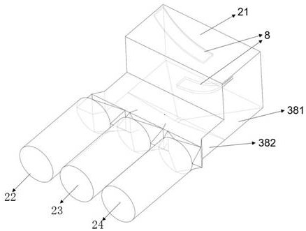
[0042] This embodiment provides a smoke distributor with area control, such as image 3 As shown, the smoke distributor 38 of this embodiment is an L-shaped structure, including a vertical part 381 and a horizontal part 382, one end of the vertical part 381 communicates with one end of the horizontal part 382, and the other end is the smoke inlet 21; the horizontal part 382 The other end is divided into multiple flue gas outlets.
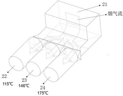
[0043] In this embodiment, there are three flue gas outlets, namely the first flue gas outlet 22 , the second flue gas outlet 23 , and the third flue gas outlet 24 . Preferably, both the vertical portion 381 and the horizontal portion 382 are rectangular in cross-section.
[0044] Due to the different flue gas temperatures at different positions in the flue, there is a problem of uneven flue gas temperature distribution in the three flue gas outlets connected to the tail of the flue gas distributor 38, such as figure 2 As shown, the temperatu...
Embodiment 2
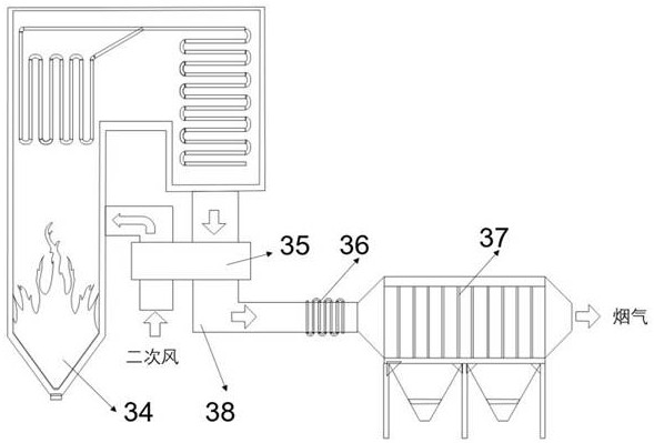
[0087] This embodiment provides a boiler system, such as figure 1 As shown, it includes a boiler 34, the top of the boiler 34 is provided with a flue gas outlet, and the flue gas outlet is connected to the flue, and an air preheater 35, a low-temperature economizer 36 and a dust collector 37 are arranged in sequence in the flue, wherein the air preheater 35 and the low-temperature The flue gas distributor 38 described in Embodiment 1 is arranged between the economizers 36 .
[0088] Further, the flue gas distributor 38 is connected to the low-temperature economizer 36 through the non-metallic expansion joint 33 , and the flue gas flows through the low-temperature economizer 36 to heat the return water and then enters the dust collector 37 . The ash hopper connection flange 1 of the flue gas distributor 38 is connected to the non-metallic compensator at the outlet of the air preheater 35 .
[0089] During operation, pulverized coal burns in the furnace to produce flue gas, and...
PUM
 Abstract
Description
Claims
Application Information
 - R&D Engineer
- R&D Manager
- IP Professional
- Industry Leading Data Capabilities
- Powerful AI technology
- Patent DNA Extraction
Browse by: Latest US Patents, China's latest patents, Technical Efficacy Thesaurus, Application Domain, Technology Topic, Popular Technical Reports.
© 2024 PatSnap. All rights reserved.Legal|Privacy policy|Modern Slavery Act Transparency Statement|Sitemap|About US| Contact US: help@patsnap.com


