Wardrobe with self-sterilization function
A wardrobe and functional technology, which is applied in the field of wardrobes with the function of suicide bacteria, can solve the problems that the wardrobe does not have the sterilization function, cannot sterilize clothes, and is inconvenient to ventilate the wardrobe, so as to prevent the breeding of bacteria, avoid peculiar smell, and facilitate ventilation.
- Summary
- Abstract
- Description
- Claims
- Application Information
AI Technical Summary
Problems solved by technology
Method used
Image
Examples
Embodiment 1
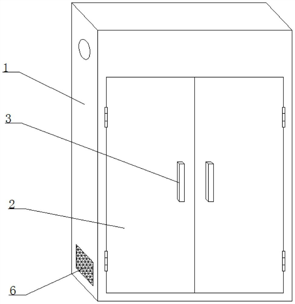
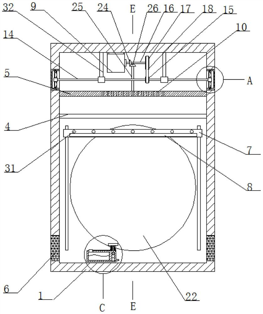
[0031] Refer Figure 1-6 A wardrobe with suicidal function, including a wardrobe main body 1, and a front surface of the wardrobe main body 1 having two door panels 2, both the front side of the two door panels 2 have a handle 3, and the wardrobe main body 1 is fixed. The straft 4 and the separator 5 are opened on the separator 5, and both sides of the wardrobe main body 1 are provided with a gas permeable mesh 6, and both sides of the wardrobe main body 1 are opened. Two grooves. A ventilation mechanism is provided in an average;
[0032] Sliding on one side of the wardrobe main body 1 slides a crossbar 7, and the crossbar 7 is provided with an ultraviolet sterilization lamp 8 and a plurality of warm lamps 31, and a motor 9 is fixed to the top inner wall of the wardrobe main body 1. The ventilation mechanism and the crossbar 7 cooperate.
[0033] In this embodiment, the ventilation mechanism includes a fixing housing 11, a first slip ring 12, and an annular fan blade 13, and the f...
Embodiment 2
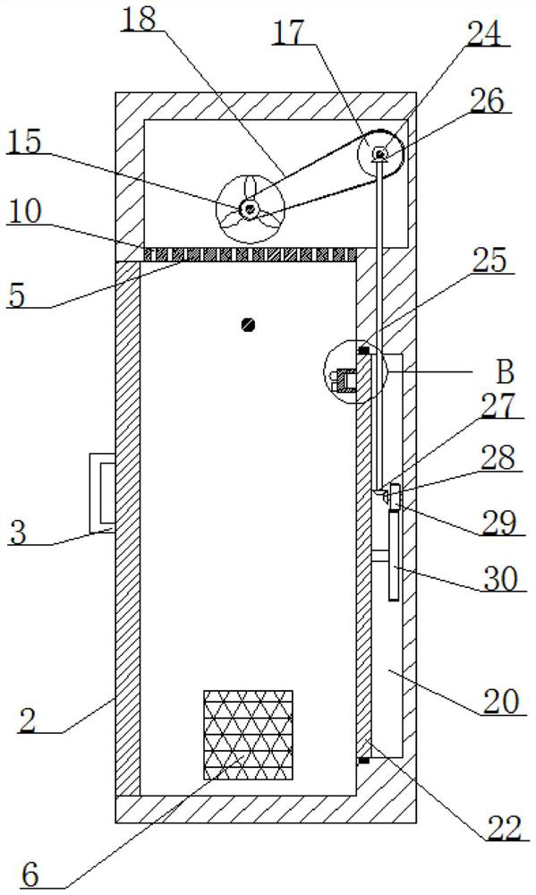
[0043] The difference from the examples is in that the wardrobe main body 1 is opened with a rotary hole on which the rotating groove 20 is turned on, and the rotating hole is rotated and mounted is attached to the second rotary rod 25, and the top end of the second rotary rod 25 is fixed. The second cone gear 26, the second cone gear 26 mesh, and the bottom end of the second rotary rod 25 extends into the rotating groove 20 and fixedly connected to the inner wall of one side of the rotary groove 20. Rotating a rotating rod, one end of the rotating rod is fixedly connected, the worm wheel, the worm gear is engaged with the worm, and the outer fixing sleeve of the rotor rod is provided with the pinion gear 29, and the other side of the rotating plate 22 is fixedly connected to the large gear 30, the large gear 30 Mes meshing with the pinion 29.
[0044] In this embodiment, the rotation shaft 16 can be rotated by the switch activation motor 9, and the rotation shaft 16 is rotated by...
PUM
 Abstract
Description
Claims
Application Information
 - R&D Engineer
- R&D Manager
- IP Professional
- Industry Leading Data Capabilities
- Powerful AI technology
- Patent DNA Extraction
Browse by: Latest US Patents, China's latest patents, Technical Efficacy Thesaurus, Application Domain, Technology Topic, Popular Technical Reports.
© 2024 PatSnap. All rights reserved.Legal|Privacy policy|Modern Slavery Act Transparency Statement|Sitemap|About US| Contact US: help@patsnap.com


