
Spiral waveform vibration ion engine

A technology of ion engine and waveform vibration, applied in electromechanical devices, electrical components, etc., can solve problems that cannot be effectively solved, bulky, air pollution, etc.

Inactive Publication Date: 2021-09-14
孙克
View PDF0 Cites 0 Cited by
  • Summary
  • Abstract
  • Description
  • Claims
  • Application Information

AI Technical Summary

Problems solved by technology

Steam turbines are bulky; fuel engines cause air pollution; electric motors have low efficiency; aerospace engines such as rockets carry too much fuel, and a series of problems cannot be effectively solved.

Method used


Image

  • Spiral waveform vibration ion engine
  • Spiral waveform vibration ion engine
  • Spiral waveform vibration ion engine

Examples


specific Embodiment 1

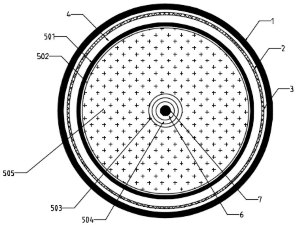
[0024] Specific embodiment 1, a kind of helical waveform vibrating ion engine, is power source with metal, liquid metal or strong electrolyte;

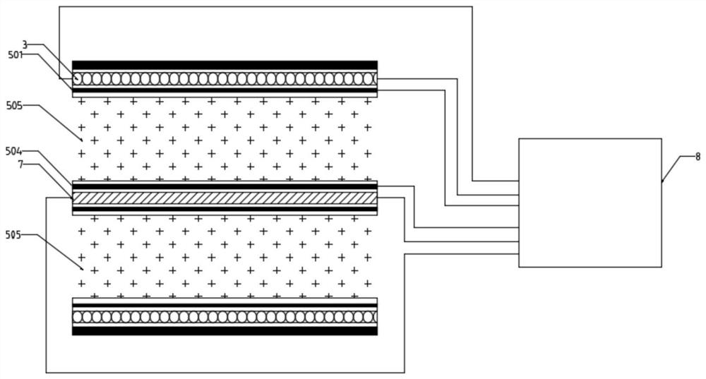
[0025] From the outermost layer to the innermost axis of the ion engine, there are sequentially provided shells 1, insulation and heat insulation layers 2, coil heating layers 3, first insulation layers 4, electrode chambers, second insulation layers 6, and magnetic field generators. stick 7;

[0026] The electrode cavity includes an outer ring 501 of the electrode cavity, a third insulating layer 502, a fourth insulating layer 503 and an inner ring 504 of the electrode cavity from the outside to the inside. Propellant 505, in the present embodiment 1, propellant 505 is metal, liquid metal;

[0027] Wherein, the two poles of the coil heating layer 3 , the outer ring 501 of the electrode cavity, the inner ring 504 of the electrode cavity and the two poles of the magnetic field generating rod 7 are all electrically connected to the AC ...


PUM


Abstract

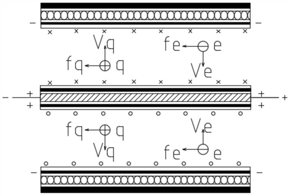
The invention discloses a spiral waveform vibration ion engine. A shell, an insulation heat insulation layer, a coil heating layer, a first insulation layer, an electrode cavity, a second insulation layer and a magnetic field generation rod are sequentially arranged from the outermost layer to the innermost layer of the ion engine. The electrode cavity sequentially comprises an electrode cavity outer ring, a third insulating layer, a fourth insulating layer and an electrode cavity inner ring from outside to inside; a propellant is filled between the third insulating layer and the fourth insulating layer; and two poles of the coil heating layer, the outer ring of the electrode cavity, the inner ring of the electrode cavity and two poles of the magnetic field generating rod are electrically connected with an alternating current power supply. The spiral waveform vibration ion engine has the beneficial effects of high efficiency and large thrust-weight ratio; cleanness and no carbon emission are realized; according to different properties of the carrier, the engine can select different metals, liquid metals or strong electrolytes as propellants; the engine can be designed to be cylindrical, disc-shaped or ring-shaped according to different shapes of carriers; and energy is saved, and long-time use can be achieved by one-time propellant filling.

Description

technical field [0001] The invention relates to the technical field of engines, in particular to a helical waveform vibration ion engine. Background technique [0002] An engine is a machine that can convert other forms of energy into mechanical energy, including internal combustion engines (reciprocating piston engines), external combustion engines (Stirling engines, steam engines, etc.), jet engines, electric motors, etc., such as internal combustion engines. Chemical energy is converted into mechanical energy. The engine is not only applicable to the power generation device, but also refers to the whole machine including the power device (such as: gasoline engine, aero engine). [0003] Existing engines come in various forms. Steam turbines are bulky; fuel engines cause air pollution; electric motors have low efficiency; aerospace engines such as rockets carry too much fuel, and a series of problems cannot be effectively solved. Contents of the invention [0004] In ...

Claims


Application Information

Patent Timeline
Patent Type & Authority Applications(China)
IPC IPC(8): H02K44/00
CPCH02K44/00
Inventor 孙克刘丽艳刘艳楠
Owner 孙克
Learn More