A real-time motion compensation method for 3D point cloud of lidar based on imu

A laser radar and three-dimensional point cloud technology, applied in radio wave measurement systems, instruments, etc., can solve the problem of unsatisfactory three-axis position change estimation, and achieve high real-time performance and robustness, three-axis angular velocity and linear acceleration accurate effect

Active Publication Date: 2022-02-01
CHINA UNIV OF MINING & TECH
View PDF10 Cites 0 Cited by
  • Summary
  • Abstract
  • Description
  • Claims
  • Application Information

AI Technical Summary

Problems solved by technology

[0003] Conventional motion compensation methods all involve the application of IMU, but IMU only performs better in three-axis angle change estimation, but not satisfactory in three-axis position change estimation. Therefore, it is necessary to design a real-time and point cloud The scheme of compensating for distortion in all directions becomes particularly important

Method used


Image

  • A real-time motion compensation method for 3D point cloud of lidar based on imu
  • A real-time motion compensation method for 3D point cloud of lidar based on imu
  • A real-time motion compensation method for 3D point cloud of lidar based on imu

Examples


Embodiment 1

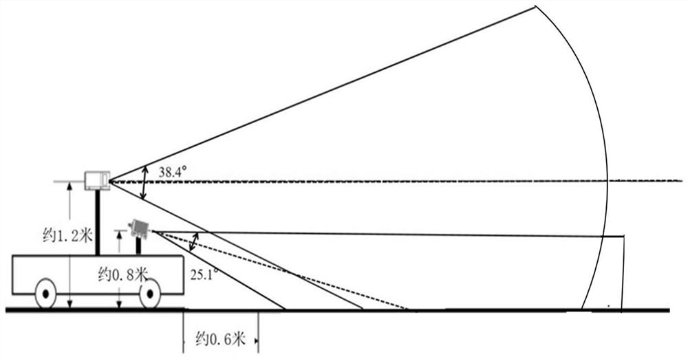
[0131] Such as figure 1 As shown, through the analysis of the parameters of the two lidars in the manual, the Horizon has a higher point cloud coverage in the field of view. It is installed directly in front of the experimental vehicle. Since the vertical viewing angle of the Horizon is 25.1°, the Horizon will It is installed with a downward inclination of about 12.5°, which makes the upper limit of Horizon's vertical viewing angle close to the horizontal, which can effectively deal with low-altitude and ground obstacles and maintain a high detection distance. Compared with the Horizon radar, the Mid-100 radar has a larger field of view, especially the vertical field of view reaches 38.4°, so it is installed horizontally on the top of the experimental vehicle, and the IMU is built into the Horizon, which saves the IMU and Horizon calibration steps.

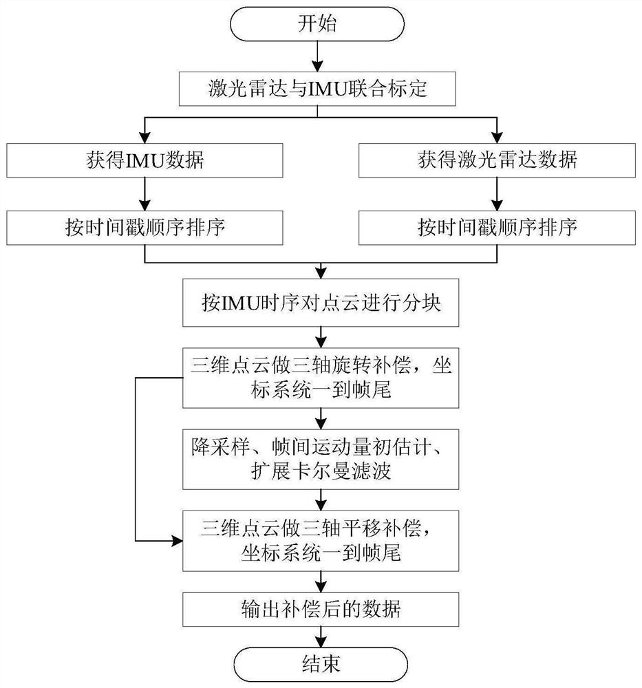
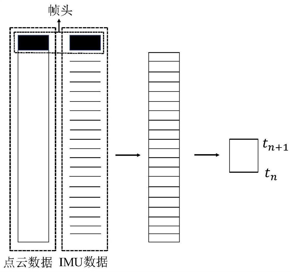
[0132] According to the sampling frequency of the IMU, the lidar 3D point cloud data is divided into blocks

[0133] Such as ...


PUM


Abstract

The invention discloses a real-time motion compensation method for three-dimensional point cloud of laser radar based on IMU. Firstly, time axis synchronization and space coordinate system 1 are performed on the laser radar and IMU used for the realization of the method of the invention, and laser The radar 3D point cloud data and the IMU data are sorted separately; secondly, a LiDAR 3D point cloud rotation compensation method based on data block division is proposed, and each frame of LiDAR 3D point cloud data is Carry out data block division, and obtain the three-axis rotation transformation matrix of each data point relative to the end of the frame according to the above data block division idea R , and perform three-axis rotation compensation on the lidar 3D point cloud data; finally, estimate the inter-frame motion of the point cloud according to the rotation-compensated point cloud data frame T , and perform translation compensation on the point cloud data. Compared with traditional methods, this method has higher real-time performance and robustness.

Description

technical field [0001] The invention relates to the field of unmanned driving, in particular to an IMU-based method for real-time motion compensation of three-dimensional laser radar point clouds. Background technique [0002] In unmanned driving technology, environmental perception is an important part, and a large number of sensors constitute an important part of environmental perception. At present, the sensors that are widely used for environmental perception are mainly cameras, millimeter-wave radars, lidars, and ultrasonic detectors. Among them, lidar occupies a dominant position. It mainly emits a large number of laser beams through the laser head, scans the principle of reflecting on the object and then receives it. It can perform long-distance high-precision measurement and static and dynamic obstacle detection tasks. As a visual sensor, the camera can provide rich perceptual information for unmanned vehicles. The disadvantage is that it does not contain distance i...

Claims


Application Information

Patent Timeline
Patent Type & Authority Patents(China)
IPC IPC(8): G01S7/497
CPCG01S7/497
Inventor 王军赵子豪李玉莲申政文潘在宇刘欢
Owner CHINA UNIV OF MINING & TECH
Why Eureka
Try Eureka