
Virtual sensor backup control method and modeling method and device

A technology of virtual sensors and control methods, applied in heating and ventilation control systems, heating methods, mechanical equipment, etc., to solve problems such as system failure to operate normally

Pending Publication Date: 2021-09-14
GD MIDEA HEATING & VENTILATING EQUIP CO LTD +1
View PDF5 Cites 0 Cited by
  • Summary
  • Abstract
  • Description
  • Claims
  • Application Information

AI Technical Summary

Problems solved by technology

[0003] The purpose of the embodiment of the present application is to provide a virtual sensor backup control method, device, electronic equipment, and storage medium, and use the virtual sensor after the actual operation data correction built in the system to perform backup operation, so as to solve the problem caused by the failure of the sensor in the existing method. system is not functioning properly

Method used


Image

  • Virtual sensor backup control method and modeling method and device
  • Virtual sensor backup control method and modeling method and device
  • Virtual sensor backup control method and modeling method and device

Examples


Embodiment 1

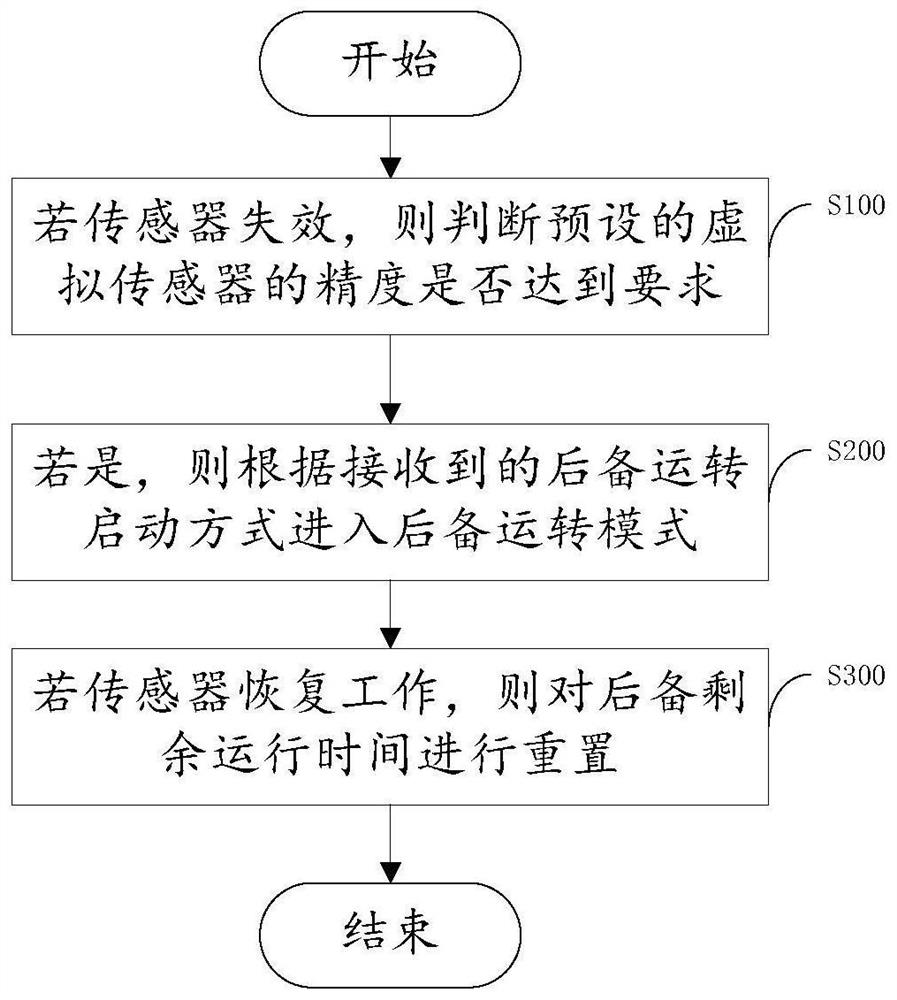
[0086] Please see figure 1 , figure 1 It is a flow chart of a virtual sensor backup control method provided by the embodiment of the present application. This method builds a virtual sensor into the system, and corrects the virtual sensor calculation model through actual operating data (components and installation environment will lead to model differences). Manual entry and automatic entry), carry out backup operation, and reset the backup operation time after the sensor recovers, so as to solve the problem that the system stops running after the sensor fails. The method specifically includes the following steps:

[0087] Step S100: If the sensor fails, then judge whether the accuracy of the preset virtual sensor meets the requirements;

[0088] First, it is necessary to construct the sensor model corresponding to the virtual sensor, such as figure 2 As shown, it is a flow chart of constructing a virtual sensor, which specifically includes the following steps:

[0089] ...

Embodiment 2

[0146] The embodiment of the present application provides a virtual sensor backup control device, such as Figure 9 Shown is the structural block diagram of the virtual sensor backup control device, which includes:

[0147] The accuracy judging module 100 is used for judging whether the accuracy of the preset virtual sensor meets the requirements if the sensor fails;

[0148] The backup start module 200 is used to enter the backup operation mode according to the received backup operation startup mode if the accuracy of the virtual sensor meets the requirements;

[0149] The reset module 300 is configured to reset the remaining running time of the backup if the sensor resumes working.

[0150] Among them, such as Figure 10 As shown, it is a block diagram of the overall structure of the virtual sensor backup control device, and the accuracy judgment module 100 includes:

[0151] Calculation module 101, for calculating the virtual sensor value;

[0152] An error module 102, ...


PUM


Abstract

The embodiment of the invention provides a virtual sensor backup control method and a modeling method and device, and relates to the technical field of air conditioners. The virtual sensor backup control method comprises the following steps of if a sensor fails, judging whether the precision of a preset virtual sensor meets the requirement or not; if yes, entering into a backup operation mode according to the received backup operation starting mode; and if the sensor recovers to work, the backup remaining operation time is reset, the virtual sensor with the corrected actual operation data built in a system is used for backup operation, so that the problem that the system cannot normally operate after the sensor fails in the existing method is solved, and the operation precision during backup operation is ensured.

Description

technical field [0001] The present application relates to the technical field of air conditioning, in particular, to a virtual sensor backup control method, modeling method and device. Background technique [0002] In the current air conditioning system, the system stops running due to sensor failure, which affects the use effect of the air conditioner. In this regard, the solution currently adopted by the industry is to directly replace other sensors for operation. Since the replaced sensor cannot correctly reflect the value of the failed sensor, the system control will fail. On the one hand, it will lead to system unreliability. On the other hand, the system cannot perform well due to the need to disable some system functions. In particular, due to the large difference between the replacement sensor and the failed sensor in the dynamic process, it causes a large reliability hidden danger. Contents of the invention [0003] The purpose of the embodiment of the present a...

Claims


Application Information

Patent Timeline
IPC IPC(8): F24F11/54F24F11/64F24F11/65F24F11/61F24F11/49
CPCF24F11/54F24F11/64F24F11/65F24F11/61F24F11/49
Inventor 郑春元丁云霄郭芳程
Owner GD MIDEA HEATING & VENTILATING EQUIP CO LTD
Learn More