A light prefabricated steel structure building

A prefabricated, steel structure technology, applied in the direction of construction, building structure, etc., can solve the problems of cumbersome operation process and achieve the effect of improving installation efficiency, stability and light structure

Active Publication Date: 2022-07-26
东莞市联泰钢构有限公司
View PDF0 Cites 0 Cited by
  • Summary
  • Abstract
  • Description
  • Claims
  • Application Information

AI Technical Summary

Problems solved by technology

[0004] For the related technologies mentioned above, when installing beams and columns, it is usually necessary to drive in a large number of bolts and nuts to achieve mutual connection. During this period, welding and reinforcement may also be involved. The operation process is cumbersome, and the components There is still a lot of room for improvement in the installation efficiency between

Method used


Image

  • A light prefabricated steel structure building
  • A light prefabricated steel structure building
  • A light prefabricated steel structure building

Examples


Embodiment 1

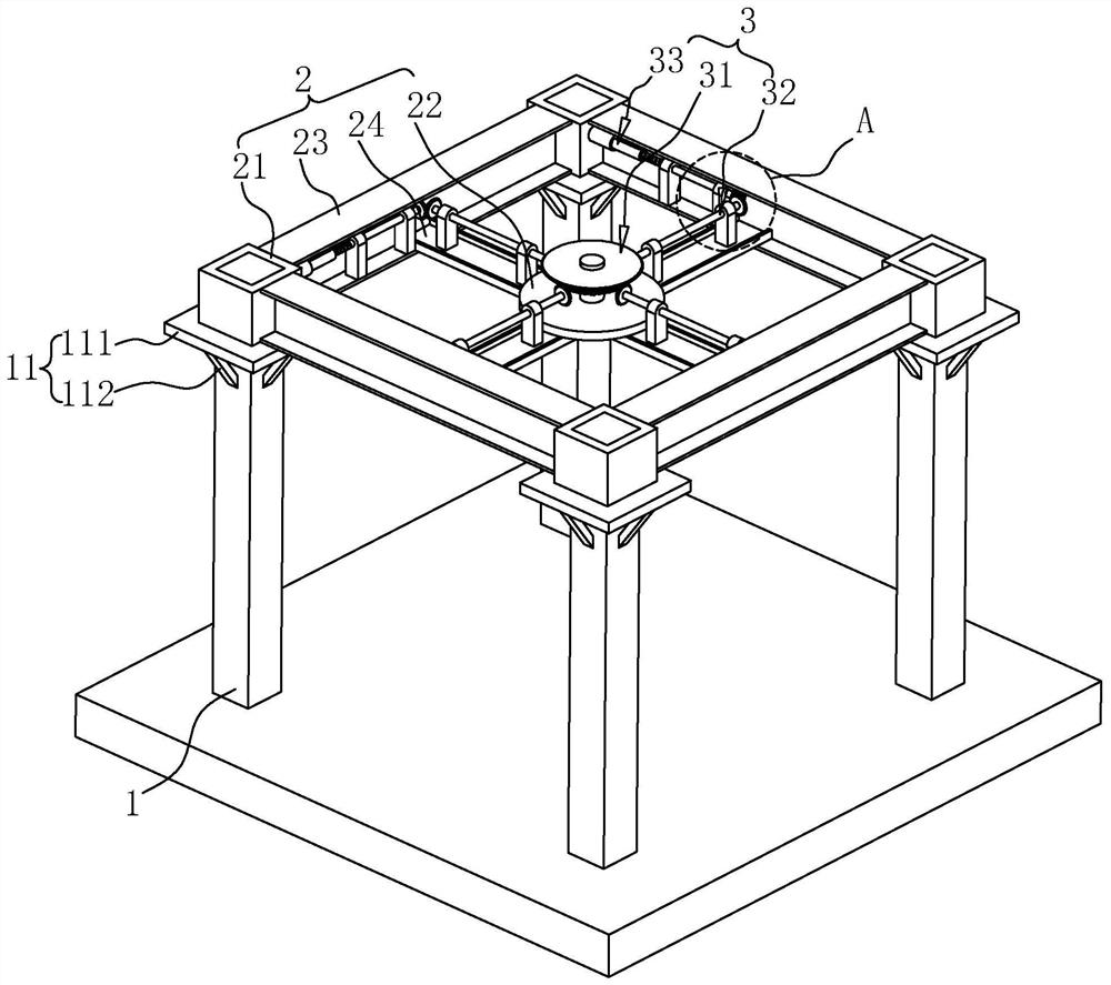
[0039] The embodiments of the present application disclose a light-weight prefabricated steel structure building. refer to figure 1 , the structural building includes a number of uprights 1 and a beam frame 2 arranged on the uprights 1, wherein, in this embodiment, the specific number of the uprights 1 is four, and the four uprights 1 are arranged in the vertical direction, and are arranged in the vertical direction. In a rectangular arrangement, the bottom end of the upright column 1 can be fixedly installed at the foundation. The installation method of the upright column 1 is in the prior art, and will not be repeated here.

[0040] The column 1 is used for supporting the beam frame 2 . Specifically, a supporting platform 11 is provided on the top of the column 1 , wherein the supporting platform 11 includes a supporting plate 111 and a reinforcing rod 112 . The support plate 111 is arranged in the horizontal direction, and the support plate 111 is provided with a socket ho...

Embodiment 2

[0059] refer to Figure 5 , the difference between this embodiment and Embodiment 1 is that the structural building also includes a buckling assembly 4 adjacent to the input shaft 311 , specifically, the buckling assembly 4 is arranged on the installation platform 22, The input shaft 311 is locked and fixed, so as to reduce the possibility of the input shaft 311 shaking and being offset and loose when the socket portion 21 and the upright column 1 are locked.

[0060] Specifically, the snap-fit ​​assembly 4 includes a first clamping portion 41 and a second clamping portion 42 . The first clamping portion 41 and the second clamping portion 42 are respectively slidably connected to the beam frame 2 . The top is recessed from the outside to the inside and is provided with a chute 221 , and the chute 221 is adjacent to the input shaft 311 .

[0061] In addition, the first clamping portion 41 includes a first connecting arm 411, a second connecting arm 412 and a first arc-shaped c...


PUM


Abstract

The present application relates to the field of prefabricated buildings, in particular to a light-weight prefabricated steel structure building. The main points of the technical solution are: including several columns, beam frames and locking components, the beam frame has a socket part, the column is provided with a supporting platform, the socket part and the column are socketed and matched with each other, and the supporting platform is opposite to the socket part. Supporting, the locking assembly includes a power input part, a transmission part and a locking part, the power input part and the transmission part are respectively arranged on the beam frame, one end of the transmission part is connected with the power input part, and the other end of the transmission part is connected with the locking part Connected, several sets of transmission parts are connected with several sets of locking parts correspondingly, the locking parts are movably arranged on the socket parts, the top of the column is horizontally drilled with locking holes, the locking parts are inserted and matched with the locking holes, and the power input The part is used to output power, and the transmission part is used to transmit the power to the locking part so that the locking part is movably inserted into the locking hole, and the present application has the effect of improving the installation efficiency of the component.

Description

technical field [0001] The present application relates to the field of prefabricated buildings, in particular to a light-weight prefabricated steel structure building. Background technique [0002] With the rapid development of modern architectural diversity, prefabricated buildings have been widely used. Prefabricated buildings are modern industrial buildings that integrate standardized design, factory production, prefabricated construction, information management and intelligent applications. With the characteristics of fast assembly, high cost performance, energy saving and environmental protection, it is the frontier development direction of the construction industry. [0003] At present, prefabricated buildings are widely used in large buildings such as workshops and gymnasiums. They mainly use light steel structures to support the main body of the building. Here, the steel structure mainly includes components such as columns, beams, and roofs. Among them, the columns a...

Claims


Application Information

Patent Timeline
Patent Type & Authority Patents(China)
IPC IPC(8): E04B1/24
CPCE04B1/24E04B1/2403
Inventor 黄荣铃
Owner 东莞市联泰钢构有限公司
Why Eureka
Try Eureka