
Transverse moving walking track of railway beam moving trolley

A technology for walking rails and moving beam trolleys, which is applied in the directions of rails, movable rails, roads, etc.

Pending Publication Date: 2021-09-14
中铁五局集团第六工程有限责任公司 +1
View PDF13 Cites 0 Cited by
  • Summary
  • Abstract
  • Description
  • Claims
  • Application Information

AI Technical Summary

Problems solved by technology

[0003] Purpose of the present invention: Aiming at the problem that a turnout needs to be inserted on the business line to lead into the engineering line when transporting the bridge, a conveying structure that does not need to introduce the engineering line on the business line is provided

Method used


Image

  • Transverse moving walking track of railway beam moving trolley
  • Transverse moving walking track of railway beam moving trolley
  • Transverse moving walking track of railway beam moving trolley

Examples


Embodiment 1

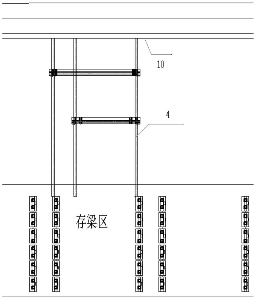
[0024] A slideway rail 4 for a railway beam-moving trolley laterally moving a traveling track. The slideway rail 4 includes a detachable slideway steel rail 4-1, a fixed slideway steel rail 4-2 and a movable slideway steel rail 4-3. The butt joint of road rail 4-1, fixed slide rail 4-2 and mobile slide rail 4-3 is connected with splint 9.

[0025] The fixed slide rail 4-2 is horizontally installed on the outside of the existing line, and a flatbed car is arranged on the existing line, and the mobile slide rail 4-3, the mobile slide rail 4-3 and the fixed slide rail 4-2 are installed on the flat cart butt ends. The other end of the fixed slide rail 4-2 is docked with the detachable slide rail 4-1 within the walking range of the gantry crane.

[0026] The slide rail 4 is provided with three, and the slide rail 4 in the middle is used as a shared track, and has different spacings with the other two slide rails 4, so as to adapt to bridge transportation of different sizes.

[00...

Embodiment 2

[0033] Such as Figure 1-Figure 4 As shown, the rail system for the lateral movement of the railway beam-moving trolley includes the detachable slideway foundation 1, the fixed slideway foundation 2, the mobile slideway foundation 3 installed on the road flat car, the slideway rail 4 and the buffer device 5 composition. The detachable slideway 1 within the running line of the gantry crane is arranged vertically to the center line of the gantry crane; the fixed slideway 2 is arranged to the edge of the platform wall 10; The track rail 4 adopts P50 steel rail, and a single slideway adopts double rails with a rail spacing of 400mm; the buffer device 5 is welded at the end of the slideway by steel plates.

[0034] Preferably, the slideway rails 4 of the above-mentioned beam-moving trolley traverse the traveling track are provided with 3 pieces in total, the distance between the running slide rails of the 24m beam is 22m, the distance between the slideway of the 32m beam is 30m, a...


PUM


Abstract

The invention discloses a transverse moving walking track of a railway beam moving trolley.The transverse moving walking track comprises slide rail steel rails (4), the slide rail steel rails (4) comprise fixed slide rail steel rails (4-2) and movable slide rail steel rails (4-3), the fixed slide rail steel rails (4-2) are transversely installed on the outer side of an existing line, a flat car is arranged on the existing line, the movable slide rail steel rails (4-3) are installed on the flat car, and the end parts of the movable slideway steel rail (4-3) and the fixed slideway steel rail (4-2) are in butt joint. The beam moving slide way is arranged on the platform, the beams stored in the precast beam field are moved to the flat car parked on the operation railway line through the beam moving slide way, and loading of the precast bridge is completed. According to the invention, the prefabricated bridge can be moved and loaded without introducing an engineering line by laying a turnout on a business line, the technical problem that the business line cannot introduce the engineering line to load and transfer the bridge by inserting and laying the turnout is effectively solved, and the temporary engineering amount and construction cost are saved.

Description

technical field [0001] The invention belongs to the technical field of railway bridge erection and transportation, and in particular relates to a track structure used for transportation bridges. Background technique [0002] During the construction of the bridge erection on the railway business line, it is necessary to use a special flatbed truck to load and transport the bridge to the bridge position for erection. Conventional railway special flatbed trucks are used to insert and lay turnouts on the business line to lead into the engineering line, and 80T gantry cranes are used to carry out bridge loading operations. A coal collection and transportation special line of a railway is divided into a decompression line and a heavy train line. The decompression line was opened in advance, resulting in the existing lines at both ends of the bridge on the heavy train line. The prefabricated T beams required for the heavy train line must be transported to the site through the busin...

Claims


Application Information

Patent Timeline
Patent Type & Authority Applications(China)
IPC IPC(8): E01B23/10
CPCE01B23/10
Inventor 龚楠富薛明胜舒建杨顺锋肖博元
Owner 中铁五局集团第六工程有限责任公司
Learn More