Pneumatic stable lifting positioning mechanism

A jacking and positioning mechanism, lifting and positioning technology, applied in the direction of lifting frame, lifting device, etc., can solve the problems of not being able to lift at the same time and lift smoothly, many repairs, and improper assembly

Pending Publication Date: 2021-09-14
KERUI AUTOMATION TECH SUZHOU
View PDF0 Cites 0 Cited by
  • Summary
  • Abstract
  • Description
  • Claims
  • Application Information

AI Technical Summary

Problems solved by technology

[0002] At present, for products with a length of more than 1000mm, the jacking and positioning lifting mechanism is driven by two or more cylinders, which cannot be lifted and lifted at the same time and smoothly. Large, and there are more repairs

Method used


Image

  • Pneumatic stable lifting positioning mechanism
  • Pneumatic stable lifting positioning mechanism
  • Pneumatic stable lifting positioning mechanism

Examples


Embodiment

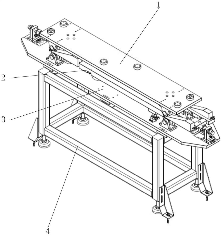
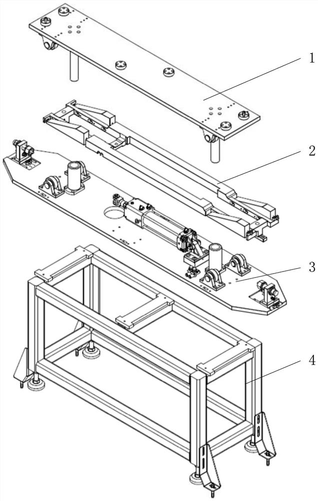
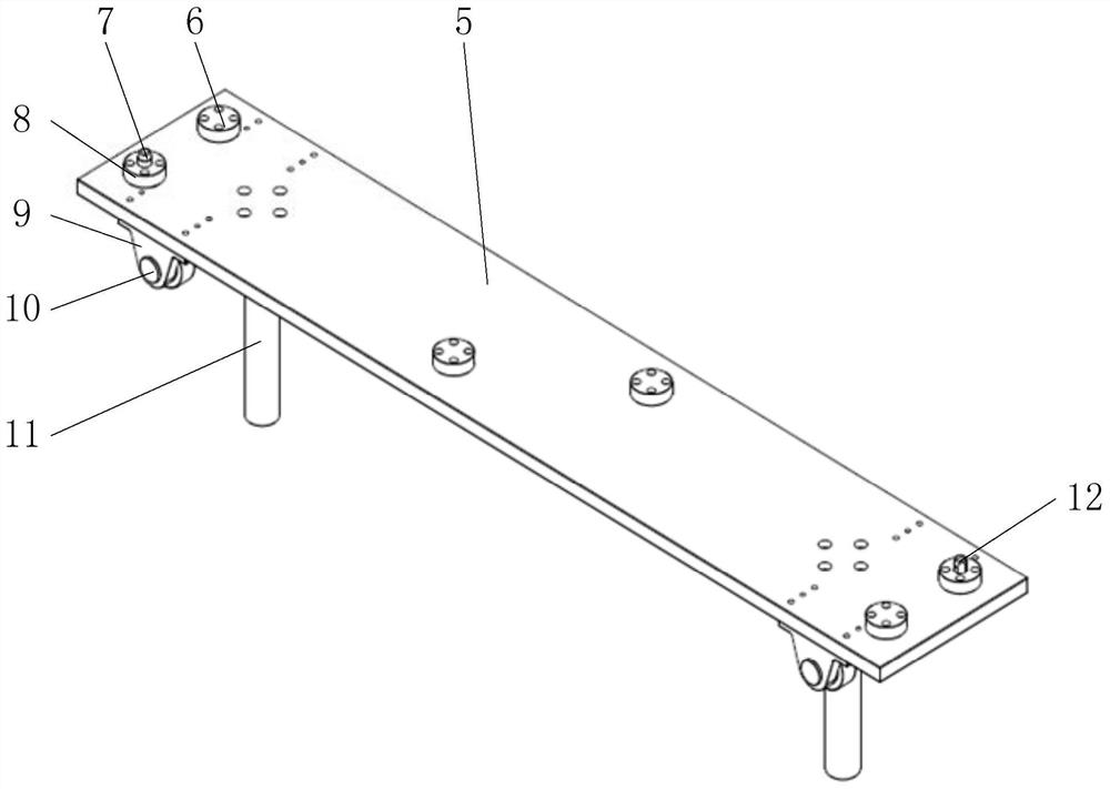
[0048] like Figure 1 to Figure 9 As shown, a pneumatic stable lifting and positioning mechanism includes a jacking and positioning mechanism 1, a connecting rod pushing block mechanism 2, a cylinder driving mechanism 3 and a fixed frame 4 from top to bottom, and the jacking and positioning mechanism 1 includes a jacking pallet 5. The upper roller 10 and the guide shaft 11, the bottom of the jacking plate 5 near the surrounding position are installed with the upper roller 10 through the upper roller fixing seat 9, and the connecting rod pushing block mechanism 2 includes a slider connecting rod 13, a cylinder Y-shaped Joint connecting block 14, forward inclined slide block 17 and rear inclined slide block 18, front end both sides of slide block connecting rod 13 are all equipped with forward inclined slide block 17, and the rear end both sides of slide block connecting rod 13 are all equipped with rear inclined slide block. Slider 18, the side of slider connecting rod 13 close...


PUM


Abstract

The invention relates to a pneumatic stable lifting positioning mechanism. The pneumatic stable lifting positioning mechanism sequentially comprises a jacking positioning mechanism, a connecting rod push block mechanism, an air cylinder driving mechanism and a fixed rack from top to bottom. After a tray of a product is in place, under the action of an air cylinder, tool positioning is automatically completed through mutual movement of rolling wheels and inclined planes, stable lifting of the product and automatic self-locking of the air cylinder are achieved, shaking is reduced, and the phenomenon of air cylinder jamming is avoided. The pneumatic stable lifting positioning mechanism is unique in design, novel in structure, capable of automatically and stably lifting, capable of automatically achieving self-locking, capable of remarkably reducing the phenomenon that standard parts are damaged, convenient to adjust and assemble and capable of improving production efficiency.

Description

technical field [0001] The invention relates to the technical field related to mechanical processing, in particular to a pneumatic stable lifting and positioning mechanism. Background technique [0002] At present, for products with a length of more than 1000mm, the jacking and positioning lifting mechanism is driven by 2 or more cylinders, which cannot be lifted and lifted at the same time and smoothly. Large, and there are more repairs. [0003] In view of the above-mentioned defects, actively research and innovate in order to create a pneumatic stable lifting positioning mechanism, so that it has more industrial utilization value. Contents of the invention [0004] In order to solve the above technical problems, the object of the present invention is to provide a pneumatic stable lifting positioning mechanism. [0005] To achieve the above object, the present invention adopts the following technical solutions: [0006] Pneumatic stable lifting and positioning mechani...

Claims


Application Information

Patent Timeline
Patent Type & Authority Applications(China)
IPC IPC(8): B66F7/20B66F7/28
CPCB66F7/20B66F7/28
Inventor 薛孟吴磊马升龙
Owner KERUI AUTOMATION TECH SUZHOU
Why Eureka
Try Eureka