Secondary alignment structure for elliptical hose shoulder injection machine
A hose shoulder injection machine, elliptical technology, applied in the direction of coating, etc., can solve the problems of production cost and production time impact
- Summary
- Abstract
- Description
- Claims
- Application Information
AI Technical Summary
Problems solved by technology
Method used
Image
Examples
Embodiment 1
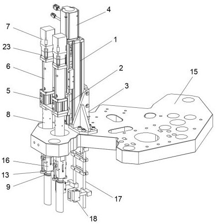
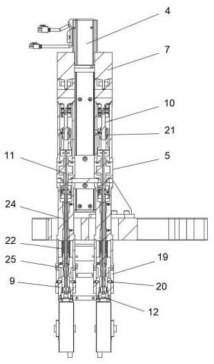
[0021] Embodiment one, such as Figure 1-2 As shown, a secondary alignment structure for an elliptical hose shoulder injection machine, including a module 1, the side surface of the module 1 is slidably connected to the connecting plate 2 and the installation bottom plate 3 through the slider, and the upper end of the module 1 is fixed A screw motor 4 is installed, the driving end of the screw motor 4 is connected to the screw drive, and the connecting plate 2 and the installation base plate 3 are threadedly connected to the screw through a screw nut;
[0022] A cylinder 5 is fixedly installed on the outer surface of the connecting plate 2, the upper end of the cylinder 5 is fixedly connected to one end of the upper casing 6, the other end of the upper casing 6 is fixedly installed with a rotating motor 7 and a reducer 23, and the lower end of the cylinder 5 is fixedly connected to the lower casing One end of 8, the upper casing 6 and the lower casing 8 are all hollow structur...
Embodiment 2
[0028] Embodiment 2, as a further solution of Embodiment 1, a limit waist hole 19 is provided on the surface of the supporter shell 16, and a limit pin 20 is movably connected in the limit waist hole 19, and the limit pin 20 is fixedly connected with the tube supporter 9. One end of the buffer spring 22 is fixedly connected to the upper end of the tube holder 9 , and the other end of the buffer spring 22 is in conflict with the lower surface of the lower casing 8 . Therefore, when pressing down, through the elastic effect of the buffer spring 22, the tube holder 9 can have a certain elastic buffer effect when inserted into the hose, and is movably connected in the limit waist hole 19 through the limit pin 20 Function, in order to realize the definition function to the position of tube supporter 9.
Embodiment 3
[0029] Embodiment 3, as a further solution of Embodiment 1, the outer surface of the ball screw 10 is movably connected with the inner cavity of the upper housing 6 through a ball spline 21 . Through the ball spline 21 , the ball screw 10 can smoothly roll and transmit torque in the inner cavity of the upper housing 6 , which further improves the load capacity of the ball screw 10 .
PUM
 Abstract
Description
Claims
Application Information
 - R&D Engineer
- R&D Manager
- IP Professional
- Industry Leading Data Capabilities
- Powerful AI technology
- Patent DNA Extraction
Browse by: Latest US Patents, China's latest patents, Technical Efficacy Thesaurus, Application Domain, Technology Topic, Popular Technical Reports.
© 2024 PatSnap. All rights reserved.Legal|Privacy policy|Modern Slavery Act Transparency Statement|Sitemap|About US| Contact US: help@patsnap.com


