
Single-chip microcomputer base with damping function

A technology of single-chip microcomputer and machine base, which is applied in manufacturing tools, auxiliary devices, auxiliary welding equipment, etc., can solve the problems of skewed pins, affecting the quality of single-chip microcomputers, and collision between pins and mounting holes.

Inactive Publication Date: 2021-09-14
李慧敏
View PDF0 Cites 0 Cited by
  • Summary
  • Abstract
  • Description
  • Claims
  • Application Information

AI Technical Summary

Problems solved by technology

[0003] Based on the inventor's discovery above, the existing ones mainly have the following deficiencies, such as: when installing and fixing the single-chip microcomputer, insert its pins into the mounting holes and cooperate with the splint to fix them; There is a certain gap between the mounting holes. When the single-chip microcomputer is welded, it will produce a slight vibration. During the vibration process, the vibration is easily transmitted to the position of the pins, so that the pins collide with the inside of the mounting holes, resulting in pins. Skew, affecting the quality of the microcontroller

Method used


Image

  • Single-chip microcomputer base with damping function
  • Single-chip microcomputer base with damping function
  • Single-chip microcomputer base with damping function

Examples


Embodiment 1

[0029] as attached figure 1 to attach Figure 6 Shown:

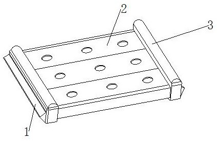
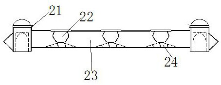
[0030] The invention provides a single-chip microcomputer base with a shock-absorbing function, and its structure includes an extension board 1, an insertion board 2, and a clamping board 3. The extension board 1 is welded and connected to the outside of the clamping board 3, and the insertion board 2 is embedded and connected. Between the clamping plates 3; the inserting plate 2 is composed of a clip 21, a mounting hole 22, a horizontal plate 23, and a top block 24. The clip 21 is movably engaged on the left and right sides of the upper end of the horizontal plate 23, and the installation The hole 22 is connected by riveting to the upper end of the top block 24 , and the top block 24 is welded to the inner lower end of the horizontal plate 23 .

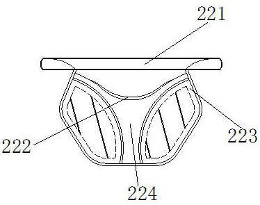
[0031] Wherein, the installation hole 22 is composed of a fitting device 221, an insertion ring 222, a curved plate 223, and an extruding device 224. The laminating device 22...

Embodiment 2

[0038] As attached 7 to attached Figure 9 Shown:

[0039]Wherein, the laminating device 221 is composed of an inner layer 211, a hollow groove 212, a pressing plate 213, and a fixing plate 214. The hollow groove 212 is located between the pressing plates 213, and the pressing plate 213 is embedded and connected to the fixing plate 214. On the inner side, the fixing plate 214 is fixedly installed on the inner side of the inner layer 211, and the pressing plate 213 is symmetrically installed on the left and right sides of the hollow groove 212, and is made of elastic material. Fixed to avoid offset during processing.

[0040] Wherein, the pressing plate 213 is composed of a contact plate 131, a telescopic part 132, and a connecting plate 133. The telescoping part 132 and the connecting plate 133 are an integrated structure, and the connecting plate 133 is embedded and connected to the right side of the contact plate 131. The telescopic parts 132 are installed in a triangular ...


PUM


Abstract

The invention discloses a single-chip microcomputer base with a damping function. The single-chip microcomputer base with the damping function structurally comprises an extension plate, an insertion plate and clamping plates, the extension plate is connected to the outer sides of the clamping plates in a welded mode, and the insertion plate is fixedly connected between the clamping plates in an embedded mode. The insertion plate is composed of clamping pieces, mounting holes, a transverse plate and a top block, the clamping pieces are movably clamped to the left side and the right side of the upper end of the transverse plate, the mounting holes are connected to the upper end of the top block in a riveted mode, and the top block is connected to the lower end of the inner side of the transverse plate in a welded mode. When a workpiece slides into a clamping block, the workpiece can contact rolling buttons, then a rotating button is driven to rotate, an outer smooth ring is pulled to rotate a certain angle, an adsorption plate is driven to be attached to the outer side of a pin for fixation, the pin on the inner side is extruded and fixed through the rolling buttons which are installed in a crossed mode, so that it is guaranteed that the pin is vertically placed in the middle, certain buffering is provided through rubber sheets during machining vibration, a bending plate is matched for extrusion, the attaching area is increased, and mutual collision is avoided.

Description

technical field [0001] The invention belongs to the field of processing equipment containing a single-chip microcomputer, and more specifically relates to a single-chip microcomputer base with a shock-absorbing function. Background technique [0002] The single-chip microcomputer is a kind of integrated circuit chip. During the processing process, it needs to be installed on the designated mounting base for processing and use. The detachable splint is attached to both sides of the single-chip microcomputer, and then the splint is fixed and clamped with a clamping device. [0003] Based on the inventor's discovery above, the existing ones mainly have the following deficiencies, such as: when installing and fixing the single-chip microcomputer, insert its pins into the mounting holes and cooperate with the splint to fix them; There is a certain gap between the mounting holes. When the single-chip microcomputer is welded, it will produce a slight vibration. During the vibration...

Claims


Application Information

Patent Timeline
IPC IPC(8): B23K37/00F16F15/08
CPCB23K37/00F16F15/08
Inventor 李慧敏
Owner 李慧敏
Learn More