
Auxiliary traction device

A pulling device and pulling technology, applied in the field of medical devices, can solve problems such as difficult operation and poor stability of hand-held doctors

Pending Publication Date: 2021-09-14
山东大学齐鲁医院(青岛)
View PDF0 Cites 0 Cited by
  • Summary
  • Abstract
  • Description
  • Claims
  • Application Information

AI Technical Summary

Problems solved by technology

[0005] Therefore, the technical problem to be solved by the present invention is to overcome the problem that the other end of the traction wire connected to the diseased tissue in the prior art is held by another doctor, and when the hand-held doctor operates according to the operator's language requirements, due to the language expression Due to limitations, the operation is difficult to meet the operator's requirements, and the stability of the hand-held doctor itself is also poor, so as to provide an auxiliary pulling device that hardly requires the cooperation of other doctors

Method used


Image

  • Auxiliary traction device
  • Auxiliary traction device
  • Auxiliary traction device

Examples


Embodiment

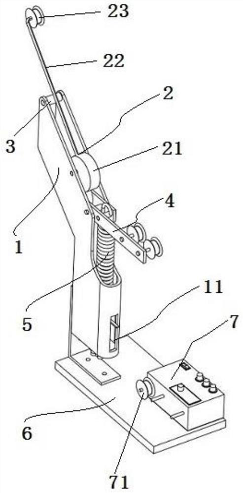
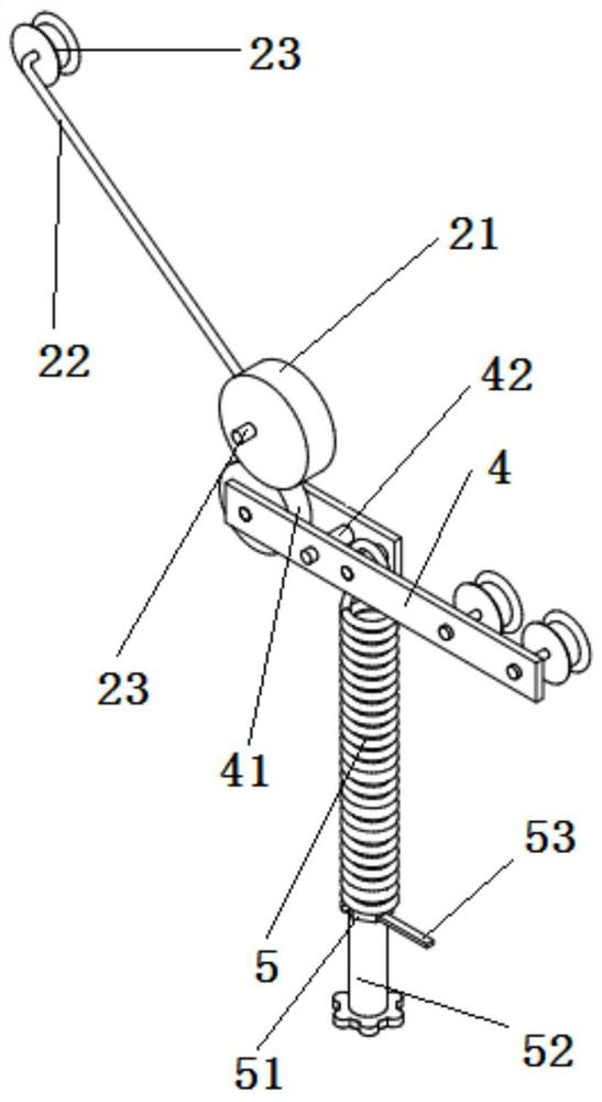
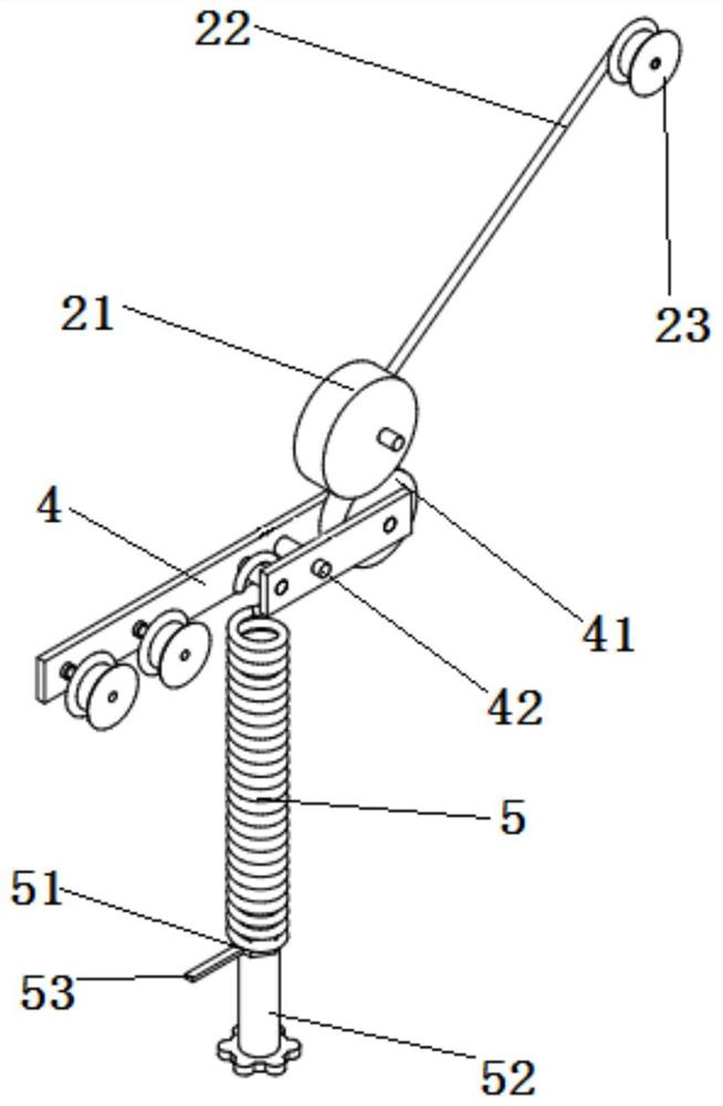
[0052] This embodiment provides an auxiliary pulling device, such as Figure 1-3 As shown, it includes: a bracket 1, a pulling member 2, a limiting member 3, a linkage structure, an elastic tension structure and a wire releasing device. Wherein: the bracket 1 is fixedly set; the pulling member 2 is rotatably installed on the bracket 1, has a first linkage 21, and a pulling rod 22, and the pulling rod 22 is provided with a The circumvention structure; the limiter 3 is arranged on the support 1 and is located on the rotation path of the pulling member 2; the linkage structure is rotatably installed on the support 1 through the second rotating shaft 42, On both sides of the second rotating shaft 42 , one side is provided with a second linkage 41 capable of cooperating with the first linkage 21 ; an elastic tension structure is connected to the other side of the linkage structure.

[0053] The pulling rod 22 has an initial position against the limit member 3 under the pulling for...


PUM


Abstract

The invention provides an auxiliary traction device. The auxiliary traction device comprises a support, a traction piece, a linkage structure, a limiting piece, an elastic tension structure and a pay-off device, the traction piece and the linkage structure are rotationally arranged on the support, the limiting piece is fixedly installed on the support, and the elastic tension structure is connected with the linkage structure. According to the auxiliary traction device, when the pay-off device rotates reversely, a traction line cannot directly pull a lesion and needs to be buffered by a traction rod, if the number of reverse rotation turns of the pay-off device is large, the traction rod can rotate by a larger angle towards the working position to buffer the pulling force of the traction line, in other words, due to the existence of the traction rod, the traction line does not suddenly act on a lesion with a relatively large force, but is gradually and slowly increased, so that the operation difficulty is reduced, and more reaction time is provided for an operator; and when in use, the auxiliary traction device can be placed on one side of an operating table, the doctor operates the pay-off device to rotate reversely while observing lesions, and after the pay-off device is operated to stop after the pay-off device reaches a proper position, the optimal traction position and traction force can be adjusted.

Description

technical field [0001] The invention relates to the technical field of medical devices, in particular to an auxiliary pulling device. Background technique [0002] Endoscopic resection has a great effect on tumor diseases or mucosal resection diseases. Endoscopic resection is performed under general anesthesia. Before the operation, a carbon dioxide gas model is established, and under the guidance of the endoscopic probe, special endoscopic instruments are used for resection. Compared with traditional open surgery, endoscopic resection has the advantages of less trauma, faster recovery and better aesthetics. Patients can resume normal diet, life and work as soon as possible. Endoscopic resection can be used for both benign diseases and malignant tumors. The representative endoscopic mucosal resection has been widely used as a mature treatment method at home and abroad. [0003] When performing endoscopic mucosal resection, various medical instruments used for lesion resect...

Claims


Application Information

Patent Timeline
IPC IPC(8): A61B17/02
CPCA61B17/0218A61B2017/0287
Inventor 李如源
Owner 山东大学齐鲁医院(青岛)
Learn More