Energy recovery circuit for isolating voltage converter and method thereof

An energy recovery and voltage isolation technology, which is applied in the direction of adjusting electrical variables, high-efficiency power electronic conversion, converting DC power input to DC power output, etc., and can solve the problem that the efficiency of the flyback circuit has not been substantially improved.

Active Publication Date: 2021-09-10
CHENGDU MONOLITHIC POWER SYST
View PDF7 Cites 0 Cited by
  • Summary
  • Abstract
  • Description
  • Claims
  • Application Information

AI Technical Summary

Problems solved by technology

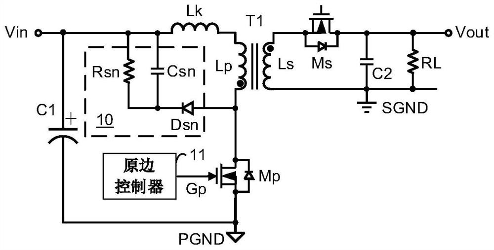
Using the snubber circuit 10 shown in Figure 1, the flyback The voltage spike of the circuit can be well suppressed, but the efficien

Method used


Image

  • Energy recovery circuit for isolating voltage converter and method thereof
  • Energy recovery circuit for isolating voltage converter and method thereof
  • Energy recovery circuit for isolating voltage converter and method thereof

Examples


Embodiment Construction

[0023] The specific embodiments of the isolated resonant converter and the control method of the present invention will be described in detail below, and it should be noted that the embodiments described here are only used for illustration and are not intended to limit the present invention. In the following description, numerous specific details are set forth in order to provide a thorough understanding of the present invention. It will be apparent, however, to one skilled in the art that these specific details need not be employed to practice the present invention. In other instances, well-known circuits, materials or methods have not been described in detail in order to avoid obscuring the present invention.

[0024] Throughout this specification, reference to "one embodiment," "an embodiment," "an example," or "example" means that a particular feature, structure, or characteristic described in connection with the embodiment or example is included in the present invention. ...


PUM


Abstract

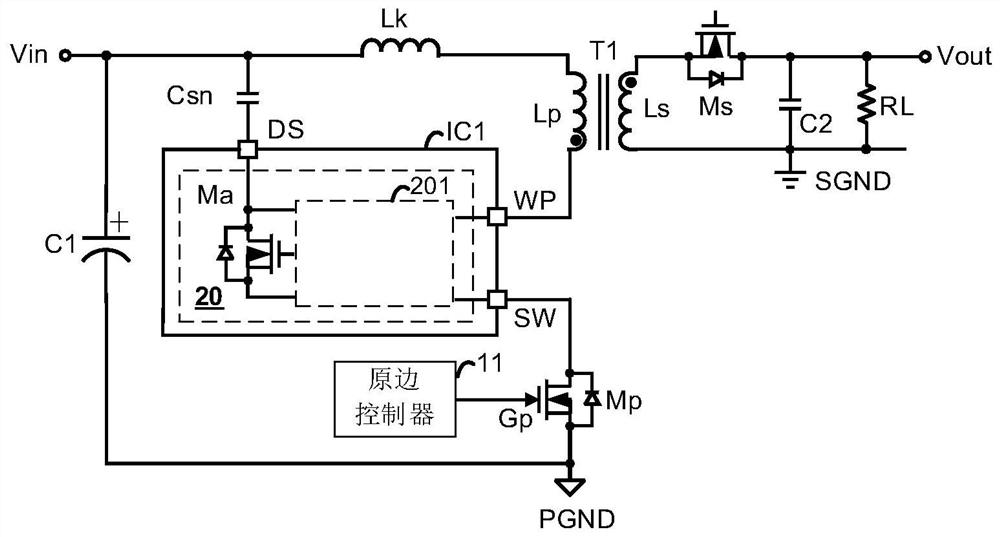
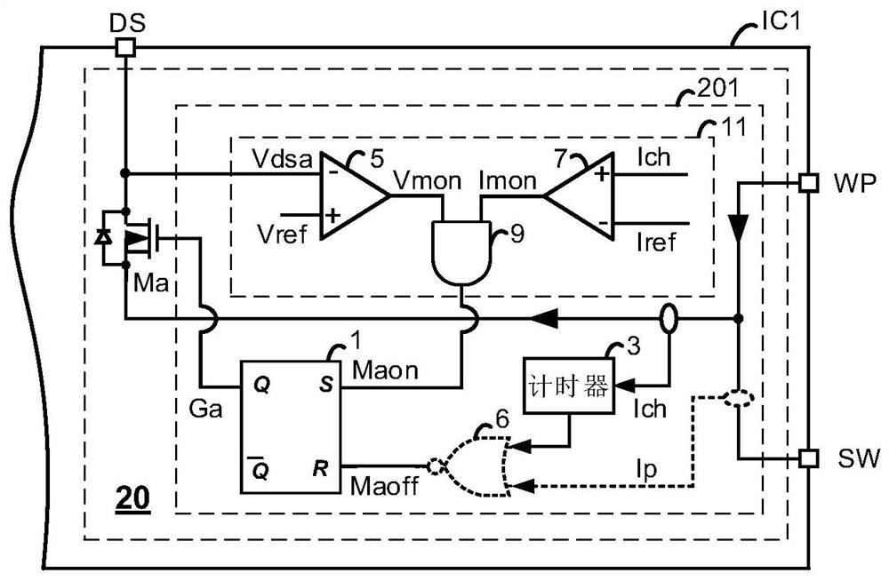
Disclosed are an energy recovery circuit for isolating a voltage converter and a method thereof. The energy recovery circuit includes: an auxiliary switch tube and a recovery control circuit. The auxiliary switch tube is coupled in series with the clamping capacitor to form a first circuit branch. The first circuit branch is coupled in parallel with a primary winding, or coupled in parallel with the primary switch tube. The recovery control circuit provides the control signal of the auxiliary switch tube. The auxiliary switch tube is turned on during the charging process of the clamp capacitor, and the auxiliary switch tube is turned off when the subsequent discharge process of the clamp capacitor ends. The charging process of the clamp capacitor is monitored according to the auxiliary switch voltage signal and the auxiliary switch current signal.

Description

technical field [0001] The present invention mainly relates to an electronic circuit, especially but not exclusively to an energy recovery circuit and an energy recovery method for an isolated voltage converter. Background technique [0002] Flyback circuits are widely used as isolation circuits in AC-to-DC converters. Much research has been going on to eliminate voltage spikes in flyback circuits and reduce voltage stress in flyback circuits. Snubber circuits are widely used because of their simple structure and low cost. figure 1 It is a circuit diagram of a conventional snubber circuit 10 . The snubber circuit 10 includes a snubber resistor Rsn, a clamp capacitor Csn and a diode Dsn, and is therefore also called an RCD snubber circuit. When the primary side control signal Gp provided by the primary side controller 11 turns off the primary side switching tube Mp, the leakage inductance Lk of the transformer T1 charges the clamping capacitor Csn through the diode Dsn, so...

Claims


Application Information

Patent Timeline
IPC IPC(8): H02M3/335H02M1/32
CPCH02M3/33576H02M3/33523H02M1/32H02M3/33569H02M1/342H02M1/0058Y02B70/10
Inventor 李彦村
Owner CHENGDU MONOLITHIC POWER SYST
Why Eureka
Try Eureka