Antenna insertion electrode structure and image display device including same

A plug-in electrode, antenna pattern technology, applied in the direction of antenna support/installation device, radiating element structure, antenna, etc., can solve the problem of increased resistance and disconnection of the sensing channel

Pending Publication Date: 2021-09-10
DONGWOO FINE CHEM CO LTD
View PDF0 Cites 3 Cited by
  • Summary
  • Abstract
  • Description
  • Claims
  • Application Information

AI Technical Summary

Problems solved by technology

Also, the connection between the sensing electrodes of the touch sensor may be broken due to the antenna, or the resistance in the sensing channel may increase

Method used


Image

  • Antenna insertion electrode structure and image display device including same
  • Antenna insertion electrode structure and image display device including same
  • Antenna insertion electrode structure and image display device including same

Examples


Embodiment Construction

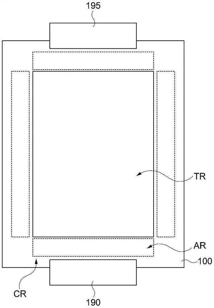
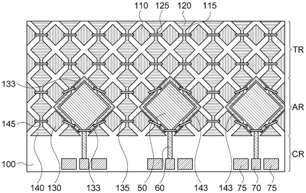
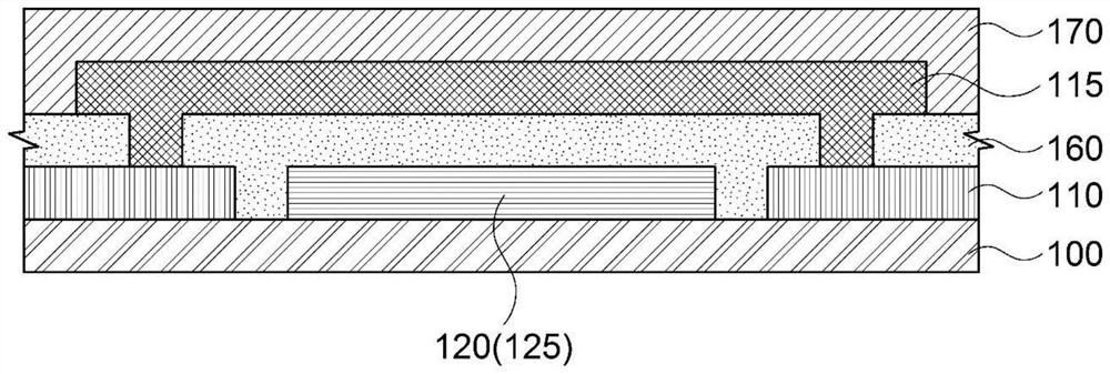
[0057]Embodiments of the present invention provide an antenna insertion type electrode structure in which an antenna pattern and a sensing electrode are arranged together in the same plane; and an image display device including the antenna insertion type electrode structure.

[0058] Hereinafter, preferred embodiments of the present invention will be described in detail with reference to the accompanying drawings. However, since the drawings attached to the present disclosure are only provided for explaining one of preferred various embodiments of the present invention so that the technical spirit of the present invention having the above-mentioned inventions can be easily understood, it should not be construed as limiting This description is shown in the accompanying drawings.

[0059] The terms "column direction" and "row direction" as used herein do not refer to absolute directions, but are used in a relative sense to refer to two directions different from each other.

[0...


PUM


Abstract

An antenna insertion electrode structure according to embodiments of the present invention comprises: a substrate layer including a touch sensing area and an antenna-touch sensing area; first sensing electrodes arranged in the touch sensing area of the substrate layer; second row sensing electrodes and second column sensing electrodes arranged in the antenna-touch sensing area of the substrate layer; second bridge electrodes which connect the second row sensing electrodes adjacent to each other in a row direction; second connection parts which connect the second column sensing electrodes adjacent to each other in a column direction; and antenna patterns. Each of the antenna patterns includes a radiation pattern which is disposed in the antenna-touch sensing area of the substrate layer, has an area larger than each of the second row sensing electrodes and the second column sensing electrodes, and avoids the second bridge electrodes and the second connection parts in a planar direction.

Description

technical field [0001] The present invention relates to an antenna insertion electrode structure and an image display device comprising the antenna insertion electrode structure, more particularly, to an antenna insertion electrode structure comprising an antenna pattern and a sensing electrode and an antenna insertion electrode structure comprising the antenna insertion electrode structure Structured image display device. Background technique [0002] Recently, for example, electronic devices capable of inputting user commands by selecting instructions displayed on a screen of an image display device using a user's finger or an object such as a touch pen or a stylus have been developed in various forms such as tablet computers. [0003] In addition, image display devices have been coupled with communication devices such as smartphones. Therefore, an antenna for realizing communication in a high frequency or ultra high frequency (eg 3G, 4G, 5G or higher) frequency band can ...

Claims


Application Information

Patent Timeline
IPC IPC(8): G06F3/044H01Q1/22
CPCG06F3/0445G06F3/0446G06F3/0448H01Q1/2266G06F2203/04112H01Q9/045H01Q1/243H01Q1/44G06F3/04164G06F2203/04111G06F3/0443G06F3/041H01Q1/38G06F3/0412H01Q21/08
Inventor 崔秉搢李在显孟昌俊
Owner DONGWOO FINE CHEM CO LTD
Why Eureka
Try Eureka