
Clamping table and machine tool

A clamping table and clamping technology, which is applied in the direction of clamping, positioning devices, driving devices, etc., can solve the problems of small processing range and difficult to meet the flexible processing of workpieces

Pending Publication Date: 2021-09-10
GUANGDONG ORIGINAL POINT INTELLIGENT TECH CO LTD
View PDF1 Cites 0 Cited by
  • Summary
  • Abstract
  • Description
  • Claims
  • Application Information

AI Technical Summary

Problems solved by technology

[0004] However, as the above-mentioned published text, if some relatively small workpieces are milled by laser, at the lowest point of the downward movement of the laser head, the bracket where the laser head is located is likely to interfere with the AC-axis turntable. The cradle-style design, in order to meet the requirements of sufficient rigidity, the position of the workpiece clamped by the turntable must be lower than the height of the A-axis, which further leads to a smaller processing range and is difficult to meet the flexible processing of the workpiece

Method used


Image

  • Clamping table and machine tool
  • Clamping table and machine tool
  • Clamping table and machine tool

Examples


Embodiment Construction

[0023] The idea, specific structure and technical effects of the present invention will be clearly and completely described below in conjunction with the embodiments and accompanying drawings, so as to fully understand the purpose, features and effects of the present invention. Apparently, the described embodiments are only some of the embodiments of the present invention, rather than all of them. Based on the embodiments of the present invention, other embodiments obtained by those skilled in the art without creative efforts belong to The protection scope of the present invention. In addition, all the connection / connection relationships mentioned in this article do not refer to the direct connection of components, but mean that a better connection structure can be formed by adding or reducing connection accessories according to specific implementation conditions. The various technical features in the invention can be combined interactively on the premise of not conflicting wi...


PUM


Abstract

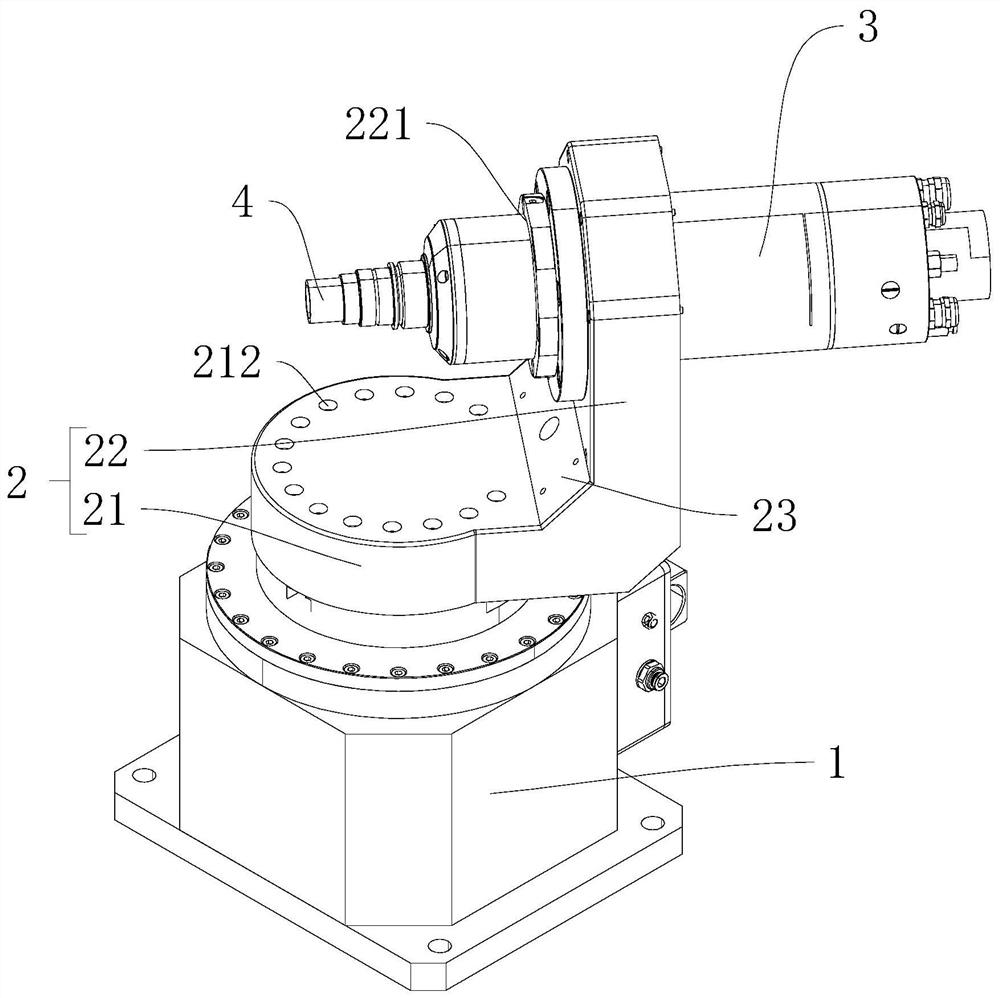
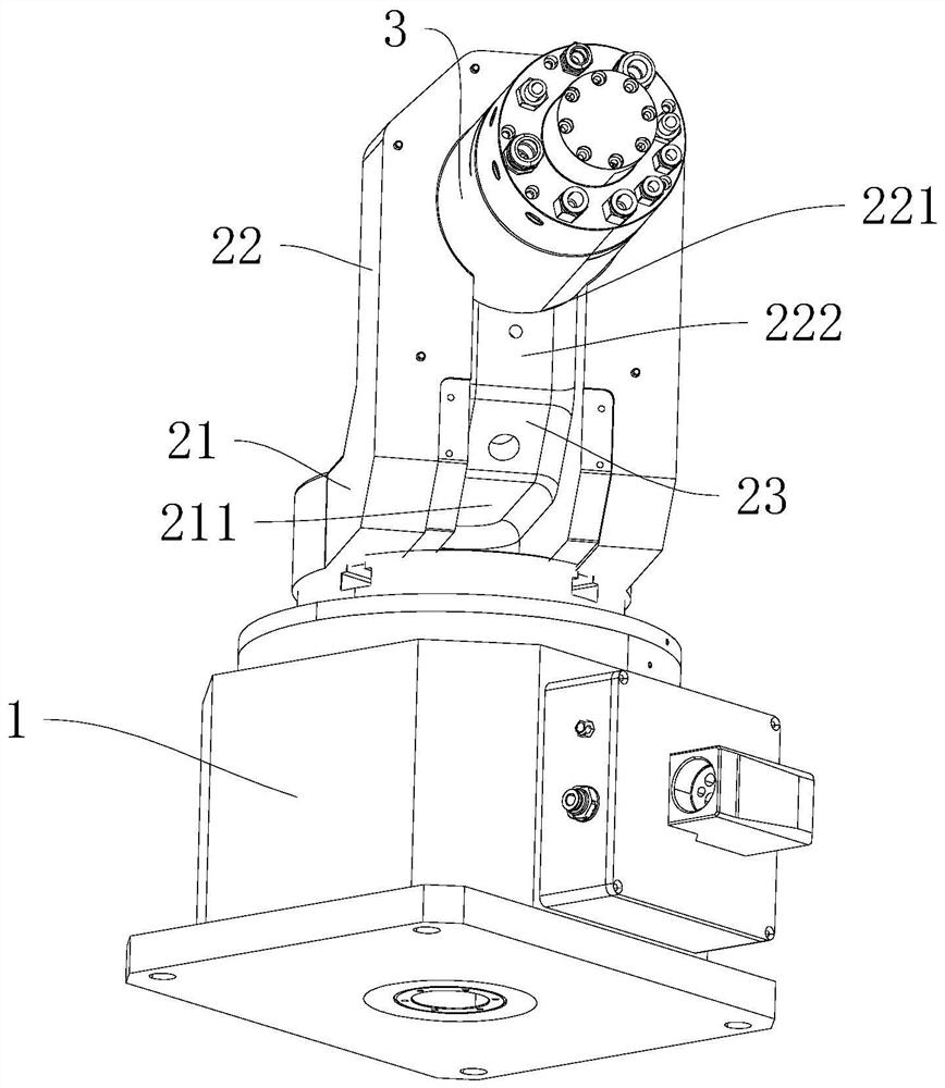
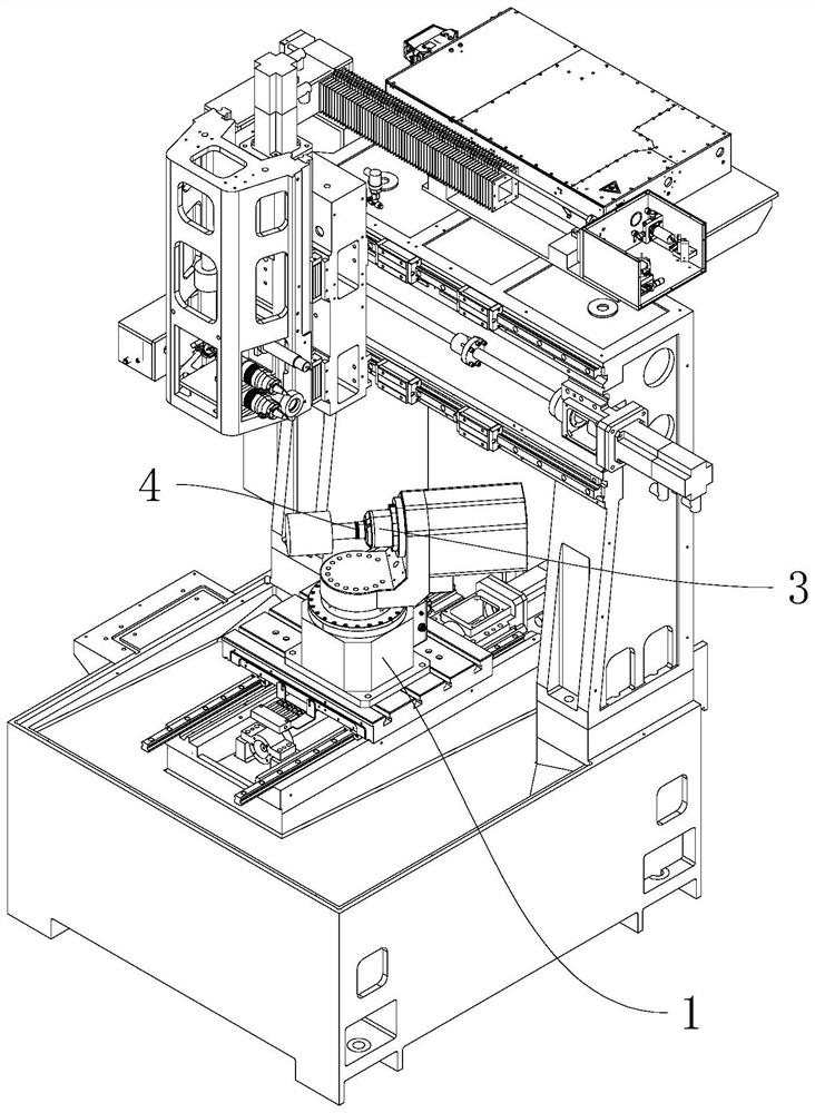
The invention discloses a clamping table and a machine tool. The clamping table comprises a rotary table, a support arranged on the rotary table, a spindle motor arranged on the support and a clamp arranged on the spindle motor; the rotating axis of the rotary table is arranged in the vertical direction, the rotary table drives the support to rotate around the rotating axis of the rotary table, an output shaft of the spindle motor is arranged in the horizontal direction, the clamp is arranged on the outer side of the support and is used for clamping a workpiece, a clamping channel is formed in the clamp, and the length direction of the clamping channel is parallel to the axis of the output shaft of the spindle motor. According to the clamping table and the machine tool, the machining area can be effectively elevated.

Description

technical field [0001] The invention relates to the technical field of fixtures, in particular to a clamping table and a machine tool. Background technique [0002] In the machining center with more than four axes, there is generally a cradle on the top, and a turntable is arranged on the cradle, so that the workpiece clamped on the turntable can be processed from multiple angles. [0003] For example, the publication number of Chinese patent application publication number is CN112207430A: "A Five-Axis Laser Milling Machine Tool". The AC-axis turntable used in the publication is used for clamping workpieces. [0004] However, as the above-mentioned published text, if some relatively small workpieces are milled by laser, at the lowest point of the downward movement of the laser head, the bracket where the laser head is located is likely to interfere with the AC-axis turntable. For the cradle-style design, in order to meet the requirement of sufficient rigidity, the position ...

Claims


Application Information

Patent Timeline
Patent Type & Authority Applications(China)
IPC IPC(8): B23Q3/06B23Q5/10
CPCB23Q3/06B23Q5/10
Inventor 赵朋陈武科曾超峰刘志峰王旭诚黄建基彭金芳
Owner GUANGDONG ORIGINAL POINT INTELLIGENT TECH CO LTD
Learn More