Fluid adsorption type laser cutting head

A laser cutting head and adsorption technology, which is applied in laser welding equipment, metal processing equipment, welding equipment, etc., can solve the problems of increased slag, incomplete removal, and slag drop

Pending Publication Date: 2021-09-10
方志
View PDF16 Cites 0 Cited by
  • Summary
  • Abstract
  • Description
  • Claims
  • Application Information

AI Technical Summary

Problems solved by technology

[0004] However, when the slag is blown away by the auxiliary gas, the flying slag will still fall on the surface of other parts of the workpiece, and

Method used


Image

  • Fluid adsorption type laser cutting head
  • Fluid adsorption type laser cutting head
  • Fluid adsorption type laser cutting head

Examples


Embodiment

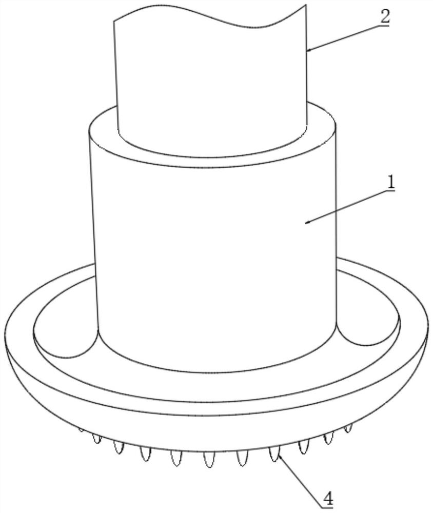
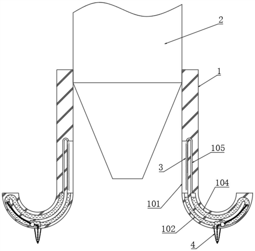
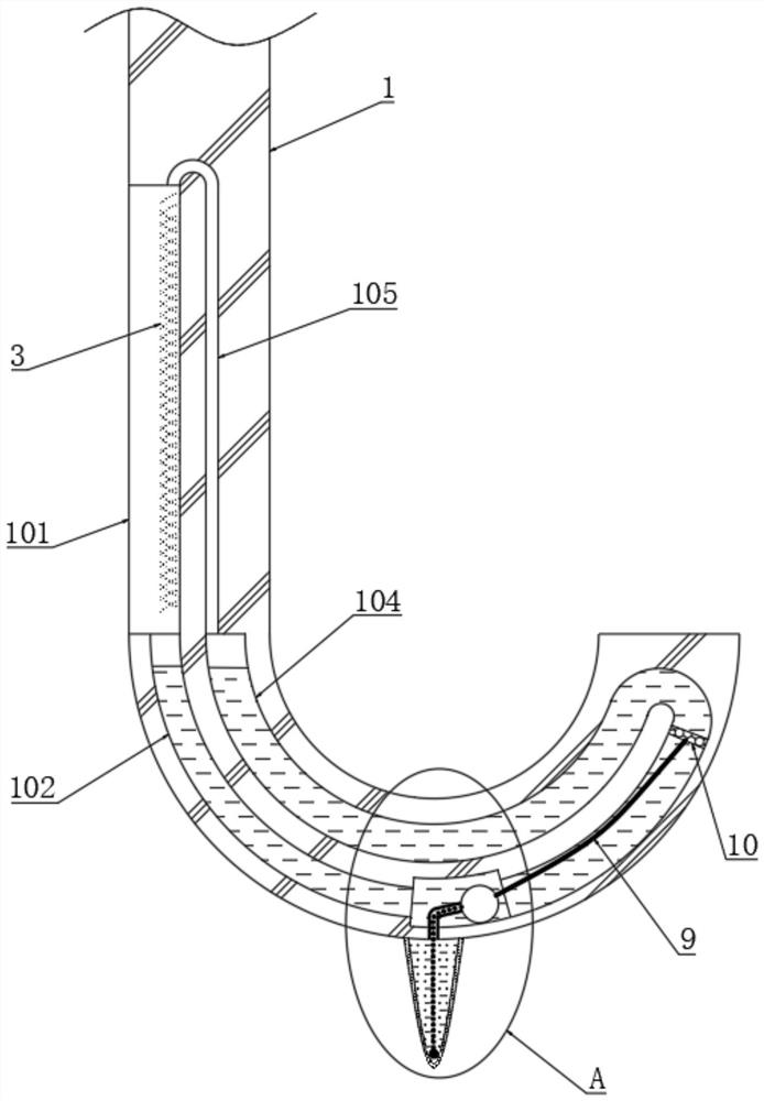
[0038] see figure 1 with figure 2 , a fluid adsorption laser cutting head, including a cutting head body 2, the outer end of the cutting head body 2 is fixedly connected with a coil tube 1, the inner surface of the coil tube 1 is provided with an annular groove 101, and the inner wall of the annular groove 101 is fixedly connected There is an adsorption wool layer 3, and the adsorption wool layer 3 is composed of a plurality of uniformly distributed rubber soft silks. The lower inner wall of the annular groove 101 is provided with a plurality of evenly distributed liquid inlet channels 102, and the liquid inlet channels 102 are far away from the edge of the annular groove 101. One end is provided with a converging channel 103, and the end of the converging channel 103 away from the liquid inlet channel 102 is provided with a liquid collecting channel 104, and the upper surface of the annular groove 101 is provided with a plurality of evenly distributed liquid outlet channels ...


PUM


Abstract

The invention discloses a fluid adsorption type laser cutting head, and belongs to the field of laser cutting heads. The fluid adsorption type laser cutting head comprises a cutting head body, and the outer end of the cutting head body is fixedly connected with a ring cylinder; and the inner surface of the ring cylinder is provided with a ring groove, and the inner wall of the ring groove is fixedly connected with an adsorption hair layer. According to the fluid adsorption type laser cutting head, when a workpiece is cut, splashing molten slag can be surrounded comprehensively, and therefore the molten slag adheres to the adsorption hair layer wetted by pure water; in the process of cutting the workpiece, a water propeller is gradually in contact with the surface of the workpiece, and is supported by the workpiece, and therefore a water pushing ball is moved along a liquid gathering flow channel; the pure water is pushed out, and sprinkled on the adsorption hair layer; on one hand, the adsorption hair layer is continuously soaked, and on the other hand, the molten slag adhering to the adsorption hair layer is cleaned, and enters a fluid inlet flow channel with water flow; and the molten slag is easy to adsorb by the adsorption hair layer continuously.

Description

technical field [0001] The invention relates to the field of laser cutting heads, more specifically, to a fluid adsorption laser cutting head. Background technique [0002] The material to be cut is irradiated with a high-power-density laser beam, so that the material is quickly heated to the vaporization temperature, and evaporates to form holes. As the beam moves to the material, the holes continuously form narrow slits to complete the cutting of the material. Cutting is one of the thermal cutting methods. In general, laser cutting requires the use of auxiliary gas, which is ejected coaxially with the laser beam to process melted and evaporated materials. The role of the auxiliary gas is as follows: [0003] One is to blow off the slag on the surface of the workpiece after the auxiliary gas is vaporized on the irradiated surface. If the auxiliary gas is not used, the slag will form burrs and attach to the cutting surface after cooling. The second is to use the gas to blo...

Claims


Application Information

Patent Timeline
IPC IPC(8): B23K26/38B23K26/70
CPCB23K26/38B23K26/702
Inventor 方志
Owner 方志
Why Eureka
Try Eureka