Multi-angle adjustable laser cutting machine

A laser cutting machine, laser cutting head technology, applied in laser welding equipment, welding equipment, metal processing equipment and other directions, can solve the problems of large space, inconvenient guide and fixation of steel frame, inconvenient to adjust the angle and so on

Active Publication Date: 2021-09-10
XUZHOU YIZHONG FORGING EQUIP
View PDF7 Cites 4 Cited by
  • Summary
  • Abstract
  • Description
  • Claims
  • Application Information

AI Technical Summary

Problems solved by technology

[0003] However, the position of the rotating assembly of the traditional laser cutting machine is fixed. When cutting a long steel frame, there is no support at the end of the steel frame, which makes the vibration frequency high during the cutting process and affects the cutting quality. If multiple guides with large distances are set The components take up a lot of space, and it is not convenient to guide and fix steel frames of different lengths. There is no protective component on the laser cutting head. When using laser cutting, if it is misoperated, it is easy to touch the laser cutting head and cause damage. The computer used for cutting control Most of the components are directly fixed on the support frame of the machine, which is not convenient to adjust the angle according to the operating habits, and most of the components used to move left and right are protected by the organ cover, and the waste is easy to fall into the concave position of the organ cover, which is not easy to clean

Method used


Image

  • Multi-angle adjustable laser cutting machine
  • Multi-angle adjustable laser cutting machine
  • Multi-angle adjustable laser cutting machine

Examples


Embodiment Construction

[0032] In order to make the technical means, creative features, goals and effects achieved by the present invention easy to understand, the present invention will be further described below in conjunction with specific embodiments.

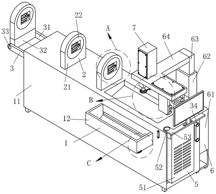
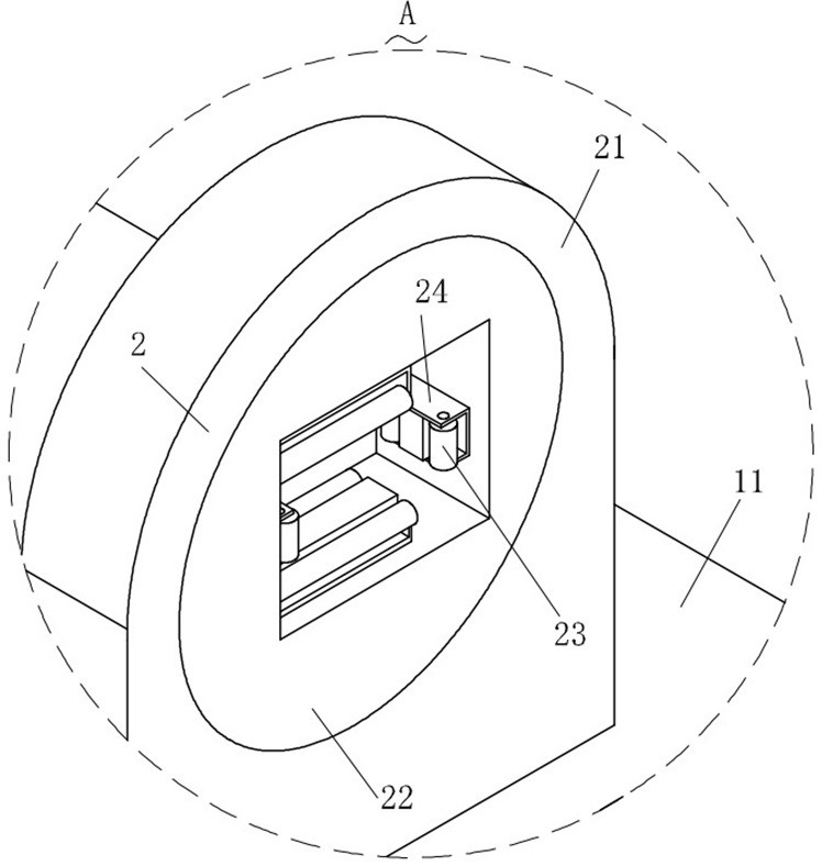
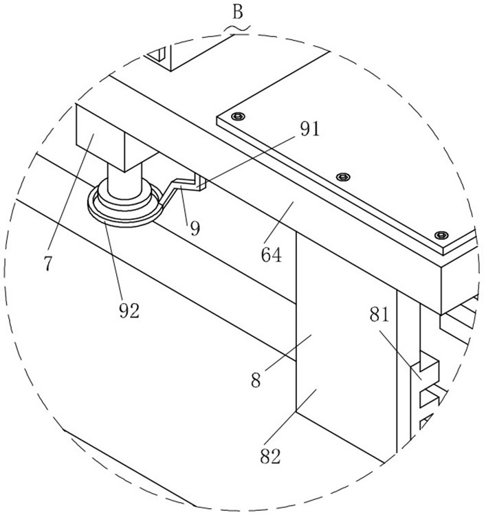
[0033] Such as Figure 1-Figure 11As shown, a multi-angle adjustable laser cutting machine according to the present invention includes a support structure 1, and a length adjustment structure 3 is provided on the support structure 1. Both the length adjustment structure 3 and the support structure 1 are provided with a A rotating structure 2 for guiding the steel frame, the supporting structure 1 is provided with a driving structure 4 for driving one of the rotating structures 2; the supporting structure 1 is provided with a moving structure 6 for adjusting the position of the laser cutting head 7, The laser cutting head 7 is fixed on the moving structure 6, and the moving structure 6 is provided with a protective structure 9 for protecting the la...


PUM


Abstract

The invention relates to the technical field of laser cutting, in particular to a multi-angle adjusting laser cutting machine. The multi-angle adjusting laser cutting machine comprises a supporting structure, a length adjusting structure is arranged on the supporting structure, and rotating structures used for guiding a steel frame are arranged on the length adjusting structure and the supporting structure, a driving structure for driving one of the rotating structures is arranged on the supporting structure; the supporting structure is provided with a moving structure used for adjusting a position of a laser cutting head, and the laser cutting head is fixed to the moving structure, a storage structure for fixing a computer is arranged on the supporting structure; a position of the rotating structure on the length adjusting structure can be conveniently adjusted through the length adjusting structure, then supporting range can be conveniently adjusted, steel frames with different lengths can be conveniently cut, operation stability is improved, meanwhile, the rotating structure on the length adjusting structure can be conveniently folded and stored, and space utilization efficiency is greatly improved.

Description

technical field [0001] The invention relates to the technical field of laser cutting, in particular to a multi-angle adjustable laser cutting machine. Background technique [0002] Laser cutting is to irradiate the steel frame with a focused high-power-density laser beam, so that the irradiated material is rapidly melted, vaporized, ablated or reached the ignition point, and at the same time, the molten material is blown away by the high-speed airflow coaxial with the beam, so as to realize the cutting of the steel frame. For example, when processing steel pipes in iron towers, steel structure supports, and steel structure grids, laser cutting equipment can be used to cut steel pipes. [0003] However, the position of the rotating assembly of the traditional laser cutting machine is fixed. When cutting a long steel frame, there is no support at the end of the steel frame, which makes the vibration frequency high during the cutting process and affects the cutting quality. If ...

Claims


Application Information

Patent Timeline
Patent Type & Authority Applications(China)
IPC IPC(8): B23K26/02B23K26/38B23K26/70
CPCB23K26/38B23K26/702B23K26/02
Inventor 高建辉高仕恒王海平
Owner XUZHOU YIZHONG FORGING EQUIP
Why Eureka
Try Eureka