Integrated submersible pump motor support
A technology of motor bracket and submersible pump, which is applied in the direction of casing/cover/support, pump, pump device, etc., can solve the problems such as failure to prevent sinking and difficulty in salvaging the submersible pump.
- Summary
- Abstract
- Description
- Claims
- Application Information
AI Technical Summary
Problems solved by technology
Method used
Image
Examples
Embodiment 1
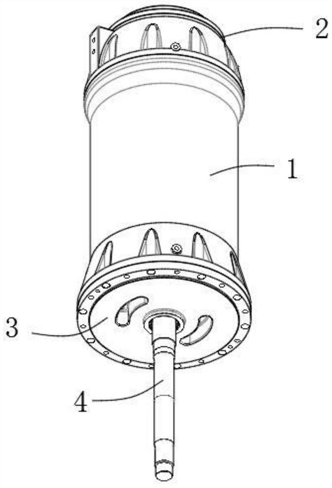
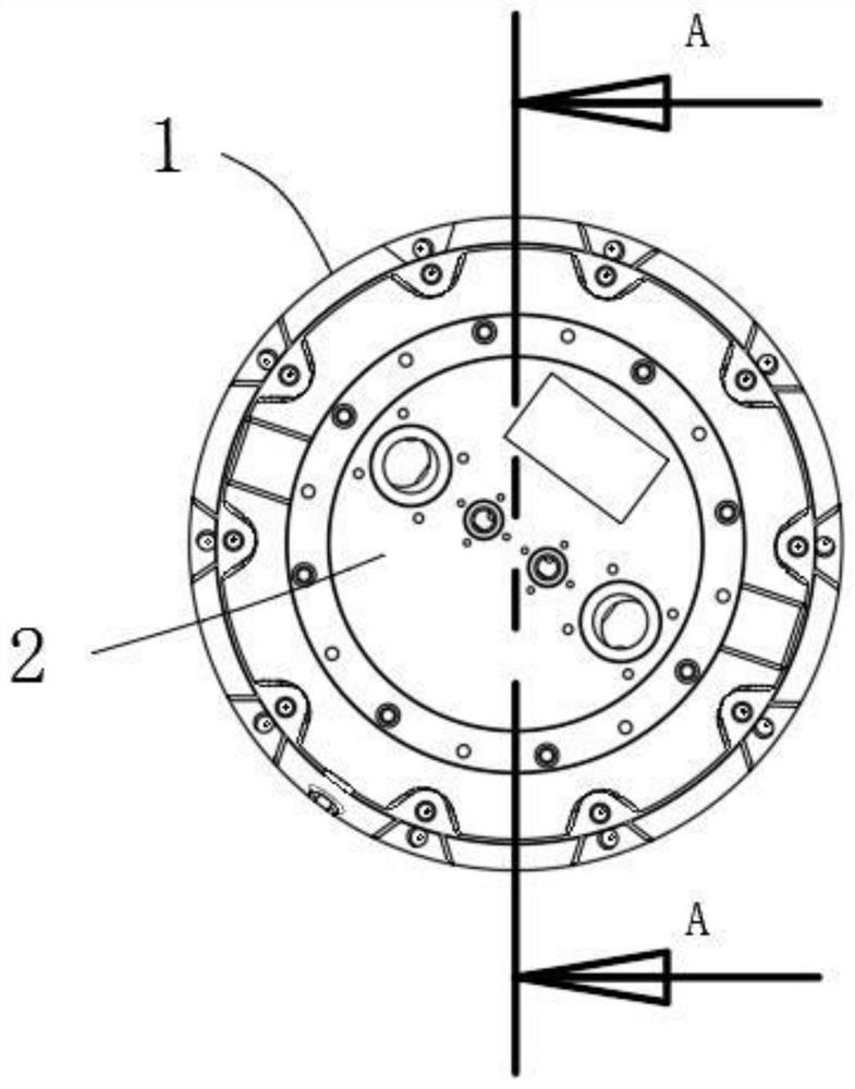
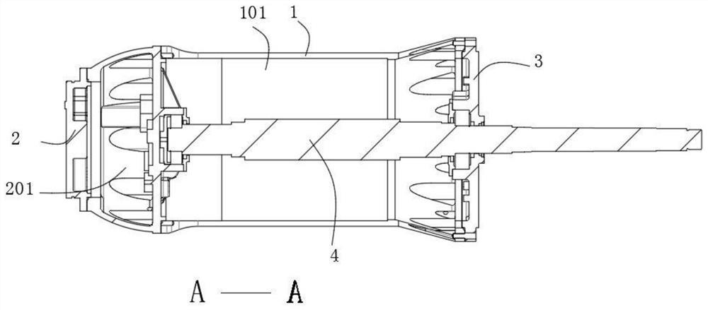
[0033] see Figure 1-4 , an integrated submersible pump motor bracket, including a casing 1, an end cover 2 and an end cover 2 3 respectively fixed at both ends of the casing 1, a rotor 4 is also arranged in the casing 1, and the inner end of the rotor 4 It is rotationally connected with the inner side of the end cover one 2, the outer end of the rotor 4 protrudes from the end cover two 3, and the casing 1 also has an inner cavity 101 for installing the stator.
[0034] A plurality of mounting shells 5 are fixed on the outside of the casing 1 in the circumferential direction, and the side of the mounting shell 5 away from the casing 1 has a gap 501, and a pole 6 is installed in the gap 501 through a rotating shaft 7, and the pole 6 The movable end of the movable end can rotate out of the notch 501, and the rotating shaft 7 is driven by the driving mechanism.
[0035] As a further improvement of the above solution, the driving mechanism is a waterproof motor fixed on the insta...
Embodiment 2
[0038] see Figure 5-9 , an integrated submersible pump motor bracket, including a casing 1, an end cover 2 and an end cover 2 3 respectively fixed at both ends of the casing 1, a rotor 4 is also arranged in the casing 1, and the inner end of the rotor 4 It is rotationally connected with the inner side of the end cover one 2, the outer end of the rotor 4 protrudes from the end cover two 3, and the casing 1 also has an inner cavity 101 for installing the stator.
[0039] A plurality of mounting shells 5 are fixed on the outside of the casing 1 in the circumferential direction, and the side of the mounting shell 5 away from the casing 1 has a gap 501, and a pole 6 is installed in the gap 501 through a rotating shaft 7, and the pole 6 The movable end of the movable end can rotate out of the notch 501, and the rotating shaft 7 is driven by the driving mechanism.
[0040] In this embodiment, different from Embodiment 1, the driving mechanism includes a gear fixedly sleeved on the ...
Embodiment 3
[0044] Please refer to Figure 7 , as a further improvement of the above scheme, the outer side of the rotating column 11 has an engaging section, the outer surface of which is in the shape of a tooth column, and the engaging section is engaged with the transmission gear 14 for transmission, and one end of the rotating column 11 is movably sleeved with Bearing seat 21, the bottom of bearing seat 21 is connected with push rod 22. Through the above structure, the operation of the rotating column 11 is more stable.
PUM
 Abstract
Description
Claims
Application Information
 - R&D
- Intellectual Property
- Life Sciences
- Materials
- Tech Scout
- Unparalleled Data Quality
- Higher Quality Content
- 60% Fewer Hallucinations
Browse by: Latest US Patents, China's latest patents, Technical Efficacy Thesaurus, Application Domain, Technology Topic, Popular Technical Reports.
© 2025 PatSnap. All rights reserved.Legal|Privacy policy|Modern Slavery Act Transparency Statement|Sitemap|About US| Contact US: help@patsnap.com


