
Newborn cradle control circuit for obstetrics and gynecology department

A technology for controlling circuits and newborns. It is applied in the direction of shaker, electrical program control, and program control in sequence/logic controllers. It can solve problems such as fatigue and failure to coax newborns to sleep in time.

Pending Publication Date: 2021-09-07
陈永英
View PDF0 Cites 0 Cited by
  • Summary
  • Abstract
  • Description
  • Claims
  • Application Information

AI Technical Summary

Problems solved by technology

[0004] In order to overcome the shortcomings that it is tiring for people to shake the shaking bed manually, and people may not be around the newborn, so they cannot coax the newborn to sleep in time, the technical problem to be solved is: provide a kind of shaker that can make people more relaxed and can coax the newborn to sleep in time. Obstetrics and gynecology neonatal shaker control circuit

Method used


Image

  • Newborn cradle control circuit for obstetrics and gynecology department
  • Newborn cradle control circuit for obstetrics and gynecology department

Examples


Embodiment 1

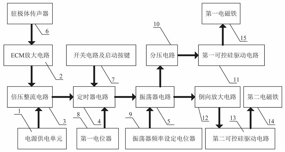
[0021] A shaker control circuit for obstetrics and gynecology neonates, such as figure 1 As shown, it includes a power supply unit 1, an ECM amplifier circuit 2, a voltage doubler rectifier circuit 3, a timer circuit 4, an oscillator circuit 5, an electret microphone 6, a switch circuit and a start button 7, a first potentiometer 8, Oscillator frequency setting potentiometer 9, voltage divider circuit 10, first thyristor drive circuit 11, reverse amplifier circuit 12, second thyristor drive circuit 13, second electromagnet 14 and first electromagnet 15, The output end of described ECM amplifier circuit 2 is connected with the input end of voltage doubler rectifier circuit 3, the input end of described ECM amplifier circuit 2 is connected with electret microphone 6, the output end of described voltage doubler rectifier circuit 3 is connected with timer The input end of the circuit 4 is connected, the switch circuit and the start button 7 and the first potentiometer 8 are all co...

Embodiment 2

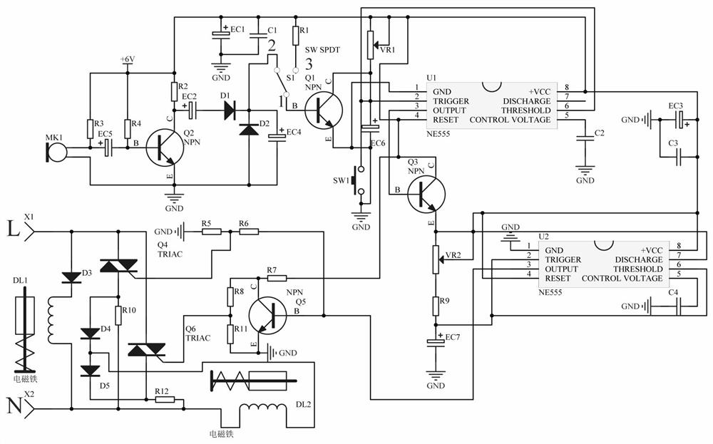
[0024] A shaker control circuit for obstetrics and gynecology neonates, such as figure 2 As shown, the ECM amplifying circuit 2 includes a triode Q2, a microphone MK1, a resistor R2, a resistor R3, a resistor R4, and an electrolytic capacitor EC5, the emitter of the triode Q2 is grounded, and the collector of the triode Q2 and the resistor R2 One end is connected, the other end of the resistor R2 is connected to +6V, the base of the triode Q2 is connected to one end of the resistor R4, the other end of the resistor R4 is connected to +6V, and the base of the triode Q2 is connected in series with the electrolytic capacitor EC5 and the microphone MK1, the other end of the microphone MK1 is grounded, one end of the resistor R3 is connected to +6V, and the other end of the resistor R3 is connected to the middle point of the series connection between the electrolytic capacitor EC5 and the microphone MK1.

[0025] The voltage doubler rectifier circuit 3 includes a triode Q1, a SPDT...


PUM


Abstract

The invention relates to the field of obstetrics and gynecology, and in particular relates to a newborn cradle control circuit for the obstetrics and gynecology department. The technical problem to be solved is to provide the cradle control circuit for neonates in the obstetrics and gynecology department, which can make people easier and make the neonates sleep in time. According to the technical scheme, the newborn cradle control circuit for the obstetrics and gynecology department comprises a power supply unit, an ECM amplifying circuit, a voltage doubling rectifying circuit and the like; and the output end of the ECM amplifying circuit is connected with the input end of the voltage doubling rectifying circuit. Through an electret microphone, crying and screaming of the neonates can be detected, a second electromagnet and a first electromagnet are controlled to be powered on intermittently, a cradle swings to make the neonates sleep, people do not need to manually push the neonates, people can feel easier, and the neonates can be timely lulled to sleep.

Description

technical field [0001] The invention relates to the field of obstetrics and gynecology, in particular to a control circuit for a rocking bed for newborns in the obstetrics and gynecology department. Background technique [0002] Newborn refers to a newborn baby. Because the mother has just given birth and cannot get out of bed, she needs to recuperate in the hospital for a period of time. Newborns are usually rested on a shaker. Newborns are relatively young and easy to cry, so they need to be shaken. The bed is used to coax the newborn to sleep. Now people generally push the rocking bed manually to make the rocking bed swing. People are more tired, and people may not be around the newborn, so they cannot coax the newborn to sleep in time. [0003] Therefore, it is necessary to design a shaker control circuit for obstetrics and gynecology neonates that can make people more relaxed and can coax newborns to sleep in time. Contents of the invention [0004] In order to overc...

Claims


Application Information

Patent Timeline
Patent Type & Authority Applications(China)
IPC IPC(8): G05B19/04A47D9/02
CPCG05B19/04A47D9/02
Inventor 陈永英
Owner 陈永英
Learn More