


Quick Research
Generate reliable direction feasibility study reports for your R&D in just a few steps.

Technical Q&A
Discover and master advanced knowledge NOW. Basics, ideas, possibilities, all at once.

Find Solutions
As an expert in R&D theories, this can generate solutions to your technical problems instantly.

Evaluate Feasibility
Analyze your overall solution with one click, know your potential R&D risks in advance.

Monitor Landscape
Get weekly tech updates, stay abreast of the latest tech innovations and key insights.
Steel wire rope bending method and device
A bending device and steel wire rope technology, applied in the field of steel wire rope bending, can solve the problems of wire rope dispersion and deformation, installation difficulties, upper and lower splints cannot be clamped normally, etc.
- Summary
- Abstract
- Description
- Claims
- Application Information
AI Technical Summary
Problems solved by technology
Method used
Image

Examples
specific Embodiment I
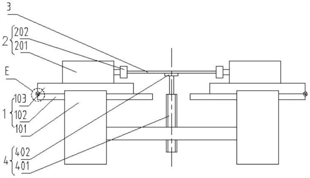
[0059] Specific embodiment 1: in order to realize above-mentioned method, as Figure 1~2 , the present invention provides a steel wire rope bending device; the device includes: a support assembly 1, two clamping assemblies 2 and a bending assembly 4; both clamping assemblies 2 are arranged on the support assembly 1, used Clamp the steel wire rope 3 to be bent at both ends and apply a torsion force consistent with its twisting direction to the steel wire rope 3 to be bent; the output end of the bending assembly 4 is in contact with the steel wire rope 3 to be bent, for The steel wire rope 3 to be bent exerts a radial force.
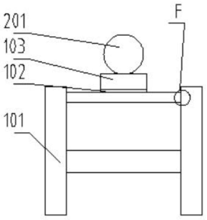
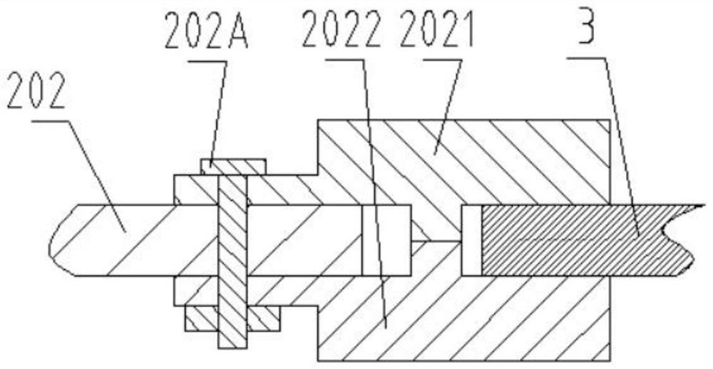
[0060] Specifically, such as image 3, the clamping assembly 2 includes: a power unit 201 and a clamping module 202; wherein, the power unit 201, such as a motor, is arranged on the support assembly 1; the clamping module 202 is arranged on the power unit 201 The output end is used to clamp the steel wire rope 3 to be bent.
[0061] The clamping module ...
specific Embodiment II
[0070] Specific embodiment II: as Figure 9-10 , the steel wire rope bending device according to the present invention may also include a centering control assembly 5: the control assembly 5 is connected to the support assembly 1 and the bending assembly 4 at the same time, and is used to The vertical movement of the control the relative movement of the support assembly 1 .
[0071] Specifically, the control assembly 5 includes: two driving racks 501, two driven racks 502, two first driven gears 503 and two second driven gears 504; The bars 501 are respectively arranged on both sides of the output end of the bending assembly 4; two driven racks 502 are arranged under the support assembly 1; Two second driven gears 504 mesh with the driven rack 502 and the first driven gear 503 on the same side of the output end of the bending assembly 4 respectively.
[0072] When this embodiment is in use, the gear racks provided on both sides of the output unit 401 mesh with the two first ...
PUM
 Abstract
Description
Claims
Application Information
 - R&D Engineer
- R&D Manager
- IP Professional
- Industry Leading Data Capabilities
- Powerful AI technology
- Patent DNA Extraction
Browse by: Latest US Patents, China's latest patents, Technical Efficacy Thesaurus, Application Domain, Technology Topic, Popular Technical Reports.
© 2024 PatSnap. All rights reserved.Legal|Privacy policy|Modern Slavery Act Transparency Statement|Sitemap|About US| Contact US: help@patsnap.com