Metal plate bending and punching integrated hydraulic press
A metal plate and integrated technology, applied in the field of hydraulic presses, can solve the problems of slowing down the work process, single structure, and increased labor operations by the operator, so as to achieve the effect of reducing labor operations and speeding up the work process
- Summary
- Abstract
- Description
- Claims
- Application Information
AI Technical Summary
Problems solved by technology
Method used
Image

Examples
Embodiment 1
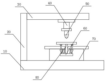
[0077] see Figure 1-6 , Metal plate bending and punching integrated hydraulic press, including installation rod 30, hydraulic cylinder 40, bending plate 50, bending table 70, base 10, strut 20;
[0078] The base 10 is used for the positioning support of the bending table 70 and the strut 20;
[0079] The support rod 20 is fixedly connected to the upper end of the base 10 and is used for the installation support of the installation rod 30;
[0080] The installation rod 30 is fixedly connected to the upper right end of the support rod 20 and is used for the installation and support of the hydraulic cylinder 40;
[0081] The hydraulic cylinder 40 is fixedly connected to the bottom end of the installation rod 30, and is used for providing the power for the bending plate 50 to work;
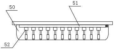
[0082] The bending plate 50 is fixedly connected to the bottom end of the hydraulic cylinder 40 for bending the metal plate;
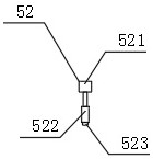
[0083] Wherein, the bending plate 50 is provided with a transmission ...
Embodiment 2
[0110] see Figure 7-8 , Since there will be a certain vibration during the punching process, the bent metal plate will shake left and right when punching, which will lead to deviations in the punched holes on the metal plate. Therefore, a fixing mechanism 60 is designed to bend the The back metal plate is fixed.
[0111] The fixing mechanism 60 is fixedly connected to the front end surface of the bending table 70 for fixing the metal plate after bending;
[0112] Wherein, the fixing mechanism 60 includes a support plate 61, a fixing table 62, a support rod 80, and a fixing assembly 63;
[0113] The fixing table 62 is fixedly connected to the front end surface of the bending table 70 and is used for the installation and support of the air pump 634;
[0114] The support rod 80 is fixedly connected to the upper end of the fixing table 62, and is used for the positioning support of the support plate 61;
[0115] The support plate 61 is fixedly connected to the upper end of the...
Embodiment 3
[0138] see Figure 9-11 , Due to the different material of the metal plate, the push block 1 334 will slide when fixing the metal plate, and the fixing will be unstable. Therefore, the suction cup 338 is designed to ensure the stability of the connection between the push block 1 334 and the metal plate.
[0139] The suction cup 338 is fixedly connected to the bottom end face of the push block 1 334, and is first adsorbed on the end face of the metal plate by the suction cup 338, and then driven by the pneumatic rod 333 to move the push block 1 334, so that the push block 1 334 is closely connected to the end face of the metal sheet. stick to each other, thereby ensuring the stability of the connection between the push block 1 334 and the metal plate.
[0140] Since there may be impurities on the metal plate, in order to ensure that the suction cup 338 can be tightly adsorbed on the end face of the metal plate, a fastening device 339 is designed for this purpose to remove the i...
PUM
 Abstract
Description
Claims
Application Information
 - Generate Ideas
- Intellectual Property
- Life Sciences
- Materials
- Tech Scout
- Unparalleled Data Quality
- Higher Quality Content
- 60% Fewer Hallucinations
Browse by: Latest US Patents, China's latest patents, Technical Efficacy Thesaurus, Application Domain, Technology Topic, Popular Technical Reports.
© 2025 PatSnap. All rights reserved.Legal|Privacy policy|Modern Slavery Act Transparency Statement|Sitemap|About US| Contact US: help@patsnap.com