
Cleaning device of particulate trap

A particle filter and cleaning device technology, which is applied in the fields of dispersed particle filtration, dispersed particle separation, chemical instruments and methods, etc., can solve the performance reduction of engine power and economy, increase of exhaust back pressure, and deterioration of diesel engine operation. and other problems, to achieve the effect of difficult cleaning, reducing volume and saving space

Pending Publication Date: 2021-09-07
SHANDONG UNIV +1
View PDF3 Cites 0 Cited by
  • Summary
  • Abstract
  • Description
  • Claims
  • Application Information

AI Technical Summary

Problems solved by technology

[0003] During the use of the particle filter, although the particle filter can filter most of the particles, the particles will accumulate in the filter during the working process of the filter, which will cause the exhaust back pressure of the diesel engine to increase. At a certain value, the work of the diesel engine begins to deteriorate significantly, resulting in a reduction in engine power and economic performance. The deposited particles must be removed in time to restore the filter to its original working state, which is what we call "regeneration". During the regeneration process of the particle filter, only the carbon deposits inside the particle filter are reduced, and the non-coke ash substances cannot be reduced and decomposed at all. These ash mainly come from the components in engine oil and fuel. Combustion, after a long period of accumulation, the ash adheres to clog the particle trap, and a series of maintenance such as regular dust cleaning must be carried out to restore part of the performance of the particle trap
[0004] The cleaning process of the particle filter usually adopts the technology of compressed air blowing. The high-pressure gas blows out the particles such as ash from the particle filter. Most of them are collected by the collection device in the dust collection bin, but there are still some ash, etc. Particles permeate the cleaning chamber, on the one hand, it may pollute the particle filter again, on the other hand, it will also cause trouble to clean the dust accumulation of the whole machine

Method used


Image

  • Cleaning device of particulate trap
  • Cleaning device of particulate trap
  • Cleaning device of particulate trap

Examples


Embodiment Construction

[0034] In order to explain the overall concept of the present invention more clearly, the following will be described in detail by way of examples in combination with the accompanying drawings.

[0035] It should be noted that many specific details have been set forth in the following description so as to fully understand the present invention, but the present invention can also be implemented in other ways different from those described here, therefore, the protection scope of the present invention is not limited by the following limitations of the specific embodiments disclosed.

[0036] In addition, in the description of the present invention, it should be understood that the terms "center", "upper", "lower", "front", "rear", "left", "right", "vertical", "horizontal" ", "Top", "Bottom", "Inner", "Outer", "Axial", "Radial", "Circumferential" and other indicated orientations or positional relationships are based on the orientations or positional relationships shown in the dra...


PUM


Abstract

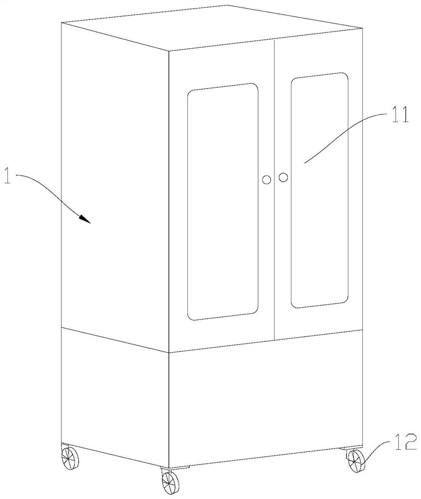
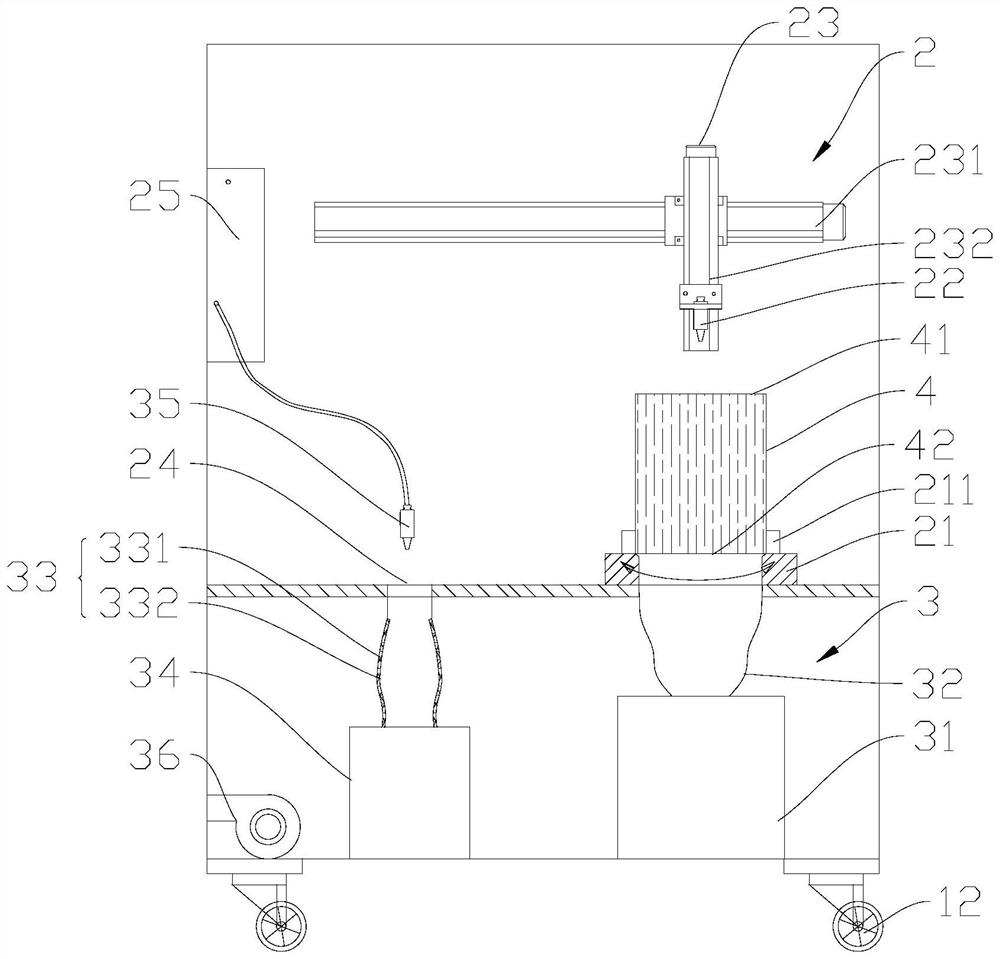
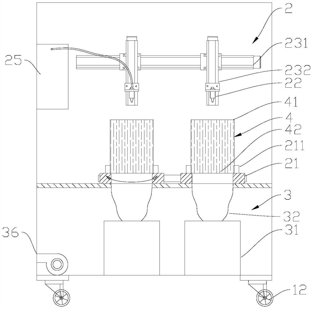
The invention relates to the field of diesel engine emission aftertreatment, and discloses a cleaning device of a particulate trap, which comprises a cleaning bin and a dust collecting bin, a fixed seat, a first nozzle and a moving mechanism are arranged in the cleaning bin, the fixed seat is used for fixing the particulate trap, the first nozzle is connected with a compressed air source to clean the particulate trap, and the moving mechanism can drive the nozzle and the fixed seat to move relatively, so that the nozzle and the ash removal end of the particulate trap move relatively to complete the cleaning action, and the cleaning bin is further provided with an exhaust hole; a first dust collecting box is arranged in the dust collecting bin, the first dust collecting box is communicated with the dust discharging end of the particle trap so as to collect particles discharged by the particle trap, a filtering device is further arranged in the dust collecting bin, and the filtering device is communicated with the exhaust hole; and the cleaning device also comprises a fan, and the fan is communicated with the dust collecting bin so as to extract gas in the dust collecting bin. Dust and other particulate matter in the cleaning bin can be cleaned, and secondary pollution to the particulate filter is relieved.

Description

technical field [0001] The invention relates to the field of diesel engine exhaust post-treatment, in particular to a cleaning device for a particle trap. Background technique [0002] Combustion of fuel will leave a large amount of harmful residues. At present, the national VI emission standard for diesel engines has a much stricter PM (particulate matter) limit than the national V. Diesel particulate filter captures particles through a surface and internal mixed filter device, which can purify 70%-90% of the particles in the exhaust gas. It is one of the most effective and direct methods to purify diesel engine particulate matter. [0003] During the use of the particle filter, although the particle filter can filter most of the particles, the particles will accumulate in the filter during the working process of the filter, which will cause the exhaust back pressure of the diesel engine to increase. At a certain value, the work of the diesel engine begins to deteriorate s...

Claims


Application Information

Patent Timeline
Patent Type & Authority Applications(China)
IPC IPC(8): B01D46/02B01D46/06B01D46/24B01D46/04B01D46/00
CPCB01D46/02B01D46/06B01D46/2411B01D46/04B01D46/0036
Inventor 程勇王永启黄超闫庆忠周广宇马庆朋陈浩
Owner SHANDONG UNIV
Learn More