Al technical title is built by PatSnap Al team. It summarizes the technical point description of the patent document.
A technology of carts and shells, applied in the field of nursing carts, which can solve problems such as easy movement and inability to switch states
Inactive Publication Date: 2021-09-07
JILIN UNIV
View PDF7 Cites 0 Cited by
Summary
Abstract
Description
Claims
Application Information
AI Technical Summary
This helps you quickly interpret patents by identifying the three key elements:
Problems solved by technology
Method used
Benefits of technology
Problems solved by technology
[0006] Aiming at the deficiencies of the prior art, the present invention provides a reproductive nursing trolley, which has the advantages of automatically switching the moving state and preventing the movement of the working plane, and solves the problem that ordinary equipment is easy to move and cannot switch states when it is working
Method used
Image
Click on the blue label to locate the original text in one second.
Reading with bidirectional positioning of images and text.
Examples
Embodiment 1
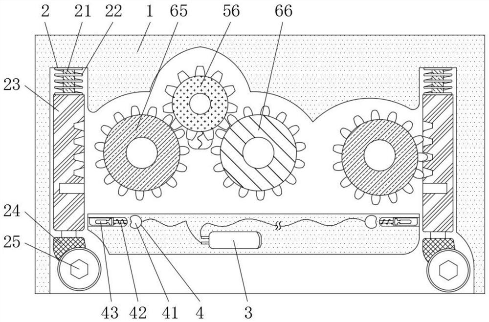
[0026] see Figure 1-2 , a nursing trolley for reproduction, comprising a housing 1, a moving mechanism 2, a power supply assembly 3, a clamping mechanism 4, a transmission mechanism 5, a matching mechanism 6, and a power mechanism 7, and both sides of the housing 1 are fixedly connected with moving Mechanism 2, the moving mechanism 2 includes a guide rod 21, a spring 22, a moving column 23, a universal block 24, and a pulley 25, the guide rod 21 is fixedly connected to the top of the housing 1, and the spring 1 22 is fixedly connected to the top of the housing 1 , the moving column 23 is movably connected to the bottom of the guide bar 21 and is fixedly connected to the spring one 22, the universal block 24 is movably connected to the bottom of the moving column 23, the pulley 25 is movably connected to the inside of the universal block 24, and the moving column 23 has a There is a through hole matched with the guide rod 21, the inner side of the moving column 23 is provided ...
Embodiment 2
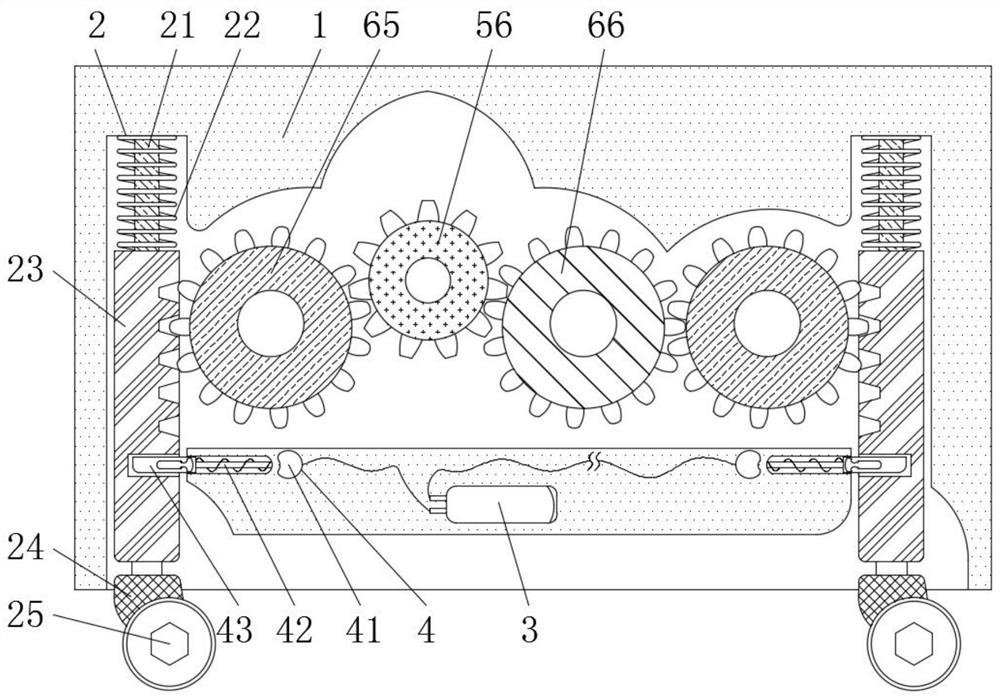
[0030] see Figure 1-4, a nursing trolley for reproduction, comprising a housing 1, a moving mechanism 2, a power supply assembly 3, a clamping mechanism 4, a transmission mechanism 5, a matching mechanism 6, and a power mechanism 7, and both sides of the housing 1 are fixedly connected with moving Mechanism 2, the moving mechanism 2 includes a guide rod 21, a spring 22, a moving column 23, a universal block 24, and a pulley 25, the guide rod 21 is fixedly connected to the top of the housing 1, and the spring 1 22 is fixedly connected to the top of the housing 1 , the moving column 23 is movably connected to the bottom of the guide bar 21 and is fixedly connected to the spring one 22, the universal block 24 is movably connected to the bottom of the moving column 23, the pulley 25 is movably connected to the inside of the universal block 24, and the moving column 23 has a There is a through hole matched with the guide rod 21, the inner side of the moving column 23 is provided w...
PUM
Abstract
The invention relates to the technical field of nursing trolleys, and discloses a nursing trolley used for the reproductive department. The nursing trolley comprises a shell, moving mechanisms, a power supply component, a clamping mechanism, a transmission mechanism, a cooperation mechanism and a power mechanism, wherein the moving mechanism is respectively fixedly connected to two sides of the shell, the power supply component is fixedly connected to the bottom of the shell, and the clamping mechanism is fixedly connected to the bottom of the shell. According to the nursing trolley used for the reproductive department, through mutual cooperation of the moving mechanisms and the clamping mechanism, the circuits of the first electromagnetic blocks are switched on, the first electromagnetic blocks are powered on to generate a magnetic field, the first electromagnetic blocks and the clamping blocks attract each other due to opposite magnetism of the opposite surfaces, and the clamping blocks overcome elastic force of elastic components to move, and therefore, clamping between each clamping block and each moving column is eliminated; and each moving column is retracted into the shell under the action of the elastic force of each first spring and the gravity of the shell, so that pulleys are separated from the ground, the shell is in direct contact with the ground, the stability of the product during working is guaranteed, the product is prevented from moving, and the stability of a working table surface is guaranteed.
Description
technical field [0001] The invention relates to the technical field of nursing carts, in particular to a nursing cart for reproductive departments. Background technique [0002] Medical trolley refers to the protective transfer medical equipment for wards. It is suitable for large hospitals, health clinics, pharmacies, mental hospitals and major daily use rotating trolleys. It can reduce the operating burden of nurses to a large extent. However, in nursing During the use of the cart, there are often situations of instability during use, which causes the working plane to shake, increases the difficulty of operation, and is not conducive to the normal use of the user. [0003] During the use of the nursing cart, when the cart stops working, the cart stops moving through the fixing of the universal wheel at the bottom. However, fixing a single universal wheel alone cannot keep the cart stable, and it will appear under the action of external force. Shaking situation, and people...
Claims
Application Information
Patent Timeline
Application Date:The date an application was filed.
Publication Date:The date a patent or application was officially published.
First Publication Date:The earliest publication date of a patent with the same application number.
Issue Date:Publication date of the patent grant document.
PCT Entry Date:The Entry date of PCT National Phase.
Estimated Expiry Date:The statutory expiry date of a patent right according to the Patent Law, and it is the longest term of protection that the patent right can achieve without the termination of the patent right due to other reasons(Term extension factor has been taken into account ).
Invalid Date:Actual expiry date is based on effective date or publication date of legal transaction data of invalid patent.