Rotor for electric machine, electric machine and motor vehicle

A technology for motor vehicles and rotors, applied in electric components, magnetic circuit rotating parts, electromechanical devices, etc., can solve problems such as reducing motor performance and loss

Pending Publication Date: 2021-09-03
AUDI AG
View PDF0 Cites 0 Cited by
  • Summary
  • Abstract
  • Description
  • Claims
  • Application Information

AI Technical Summary

Problems solved by technology

Direct spraying of the short-circuit ring with coolant therefore necessarily leads to braking t

Method used


Image

  • Rotor for electric machine, electric machine and motor vehicle
  • Rotor for electric machine, electric machine and motor vehicle
  • Rotor for electric machine, electric machine and motor vehicle

Examples


Embodiment Construction

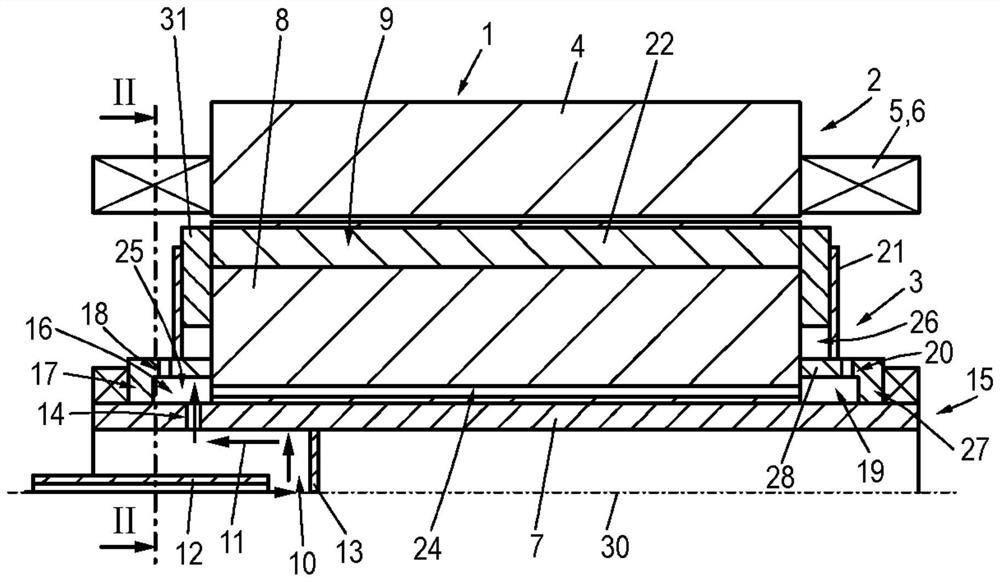
[0027] figure 1 An electric machine 1 is shown, which comprises a stator 2 and a rotor 3 rotatably mounted relative to the stator 2 . exist figure 1 A section of the electric machine 1 is shown in , where only the part of the electric machine 1 on the side of the axis of rotation 30 is shown for reasons of clarity and because of the symmetrical structure of the electric machine 1 . The stator 2 comprises a stator-side carrier 4 - for example a lamination stack - and a winding 5, in figure 1 Only the winding head 6 of the winding is shown in . The stator 2 can be cooled, for example, by means of a water jacket cooling (not shown).

[0028]The rotor 3 comprises a rotor shaft 15 and a carrier 8 , for example a lamination stack, which is coupled to the rotor shaft 15 in a non-rotatable manner, which carries a squirrel-cage winding 9 via conductor bars 22 and short-circuits connecting the conductor bars. Ring 31 is formed. Instead of the squirrel-cage winding 9 , at least one ...


PUM


Abstract

The invention relates to a rotor for an electric machine (1), comprising a rotor shaft (15), which comprises a cavity (10) for conducting a coolant through the rotor shaft, a carrier (8), which is coupled to the rotor shaft in a non-rotationally fixed manner, and at least one squirrel-cage winding (9) or winding arranged on the carrier, the radial shaft outer wall (7) of the rotor shaft has at least one through-hole (14), a cooling fluid can flow out of the cavity through a through-hole which opens into a channel system, the channel system comprising at least one annular channel and at least one carrier channel which is fluidically coupled to the annular channel and which extends in the axial direction within the carrier, a respective annular channel extends annularly around the rotor shaft outside the carrier and is formed by a respective guide part arranged on the outer wall of the shaft on the outside together with the outer wall of the shaft and/or the carrier, the respective guide part having at least one outlet opening which radially penetrates the guide part, the coolant can flow out of the channel system into the environment of the rotor through the outlet opening.

Description

technical field [0001] The invention relates to a rotor for an electric machine with a rotor shaft, a carrier coupled to the rotor shaft in a rotationally fixed manner and at least one squirrel-cage winding or winding arranged on the carrier, wherein The rotor shaft comprises a cavity for conducting coolant through the rotor shaft, wherein a radial shaft outer wall of the rotor shaft has at least one through-opening through which cooling fluid can flow out of the cavity. Furthermore, the invention relates to an electric machine and a motor vehicle. Background technique [0002] A rotary electric machine can consist of a stator and a rotor, wherein the rotor can carry a winding or—for example in the case of an asynchronous machine—a squirrel-cage winding. For example, the rotor can be formed from a rotor shaft and a carrier, which carries the winding or squirrel-cage winding and can be designed, for example, as a laminated core. When the electric machine is operated as a mo...

Claims


Application Information

Patent Timeline
IPC IPC(8): H02K1/32
CPCH02K1/32H02K9/19
Inventor M·卢克斯L·韦特劳P·苏斯M·施罗德V·切诺戈斯基K·韦伯
Owner AUDI AG
Why Eureka
Try Eureka