Method and system for preparing direction-controllable bent optical bottle
A preparation system and bending technology, applied in the field of optics, can solve problems such as low freedom, limited adjustable parameters, and inability to control the direction of light bottles, achieving the effect of simple system and low cost
- Summary
- Abstract
- Description
- Claims
- Application Information
AI Technical Summary
Problems solved by technology
Method used
Image

Examples
preparation example Construction
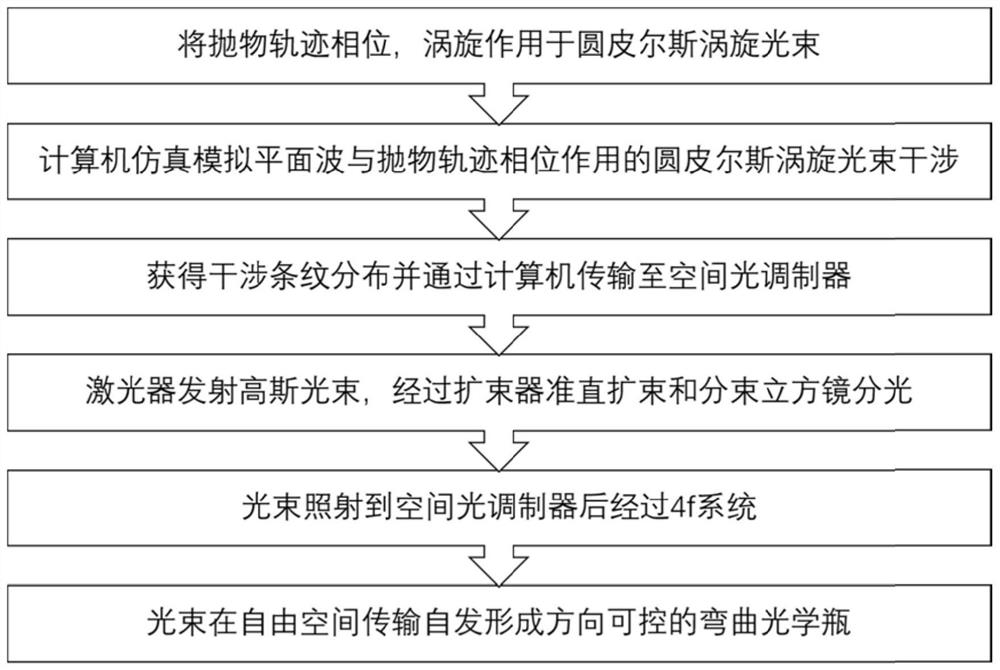
[0050] The flow chart of the method for the direction-controllable bendable optical bottle produced by the circular Pierce vortex beam propagating along the parabolic trajectory of the present invention is as follows figure 1 As shown, the preparation method of the direction-controllable curved optical bottle of the present invention comprises the following steps:
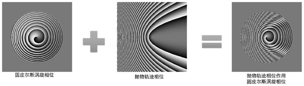
[0051] S1. Through computer simulation, the plane wave interferes with the circular Pierce vortex beam modulated by the phase of the parabolic trajectory. The amplitude and phase information of the beam is loaded on the interference fringe, and the phase hologram is obtained and transmitted to the spatial light modulator;
[0052] S2. The spatial light modulator is loaded with a phase hologram;
[0053] S3, turn on the laser to emit a Gaussian beam;
[0054] S4. The beam expander performs collimation and beam expansion processing on the Gaussian beam;
[0055] S5. The non-polarizing beam splitter cube mirror spli...
Embodiment 1
[0089] Example 1 and Figure 4 Coincidentally, under the conditions of different η values, the circular Pierce vortex beam can be transmitted along the parabolic trajectory to form optical bottles with different bending degrees. The larger the η value, the more curved the trajectory, the more obvious the curvature of the light bottle, and the longitudinal length of the light bottle body will shrink.
[0090] S1. Numerical simulation of plane waves with parameters b=0.1, r 0 =1.5, α=0, β=1, l=3, (x1,y1)=(0,0) the phase hologram after the interference of the circular Pierce vortex beam with parabolic trajectory phase, the value of η is set respectively 1000, 3000, 6000;
[0091] S2. Load the acquired phase hologram onto the spatial light modulator;
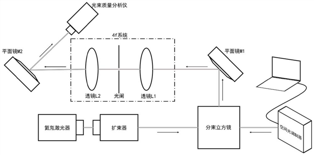
[0092] S3. Use figure 2 The optical path diagram of the experiment can make a bendable optical bottle, and the optical bottles corresponding to different η values are as follows: Figure 4 shown.
[0093] All parameters of ...
Embodiment 2
[0095] Example 2 and Figure 5 In agreement, under this condition, a circular Pierce vortex beam propagating along a parabolic trajectory in free space can produce a direction-controllable optical bottle. Combining the horizontal and longitudinal cross-sectional views, it can be seen that the circular Pierce vortex beam forms a three-dimensional closed space during the propagation process, and the bottle-shaped dark area with low light intensity in the middle is surrounded by high light intensity. A curved optical vial.
[0096]S1. Numerical simulation of plane waves with parameters b=0.1, r 0 = 1.5, α = 0, β = 1, l = 5, (x1, y1) = (0, 0), η = 1000, the phase hologram after the interference of the circular Pierce vortex beam with the parabolic trajectory phase;
[0097] S2. Load the acquired phase hologram onto the spatial light modulator;
[0098] S3. Use figure 2 The experimental optical path diagram can make a bendable optical bottle with a vortex position at (x1,y1)=(...
PUM
| Property | Measurement | Unit |
|---|---|---|
| emission peak | aaaaa | aaaaa |
Abstract
Description
Claims
Application Information
 - R&D
- Intellectual Property
- Life Sciences
- Materials
- Tech Scout
- Unparalleled Data Quality
- Higher Quality Content
- 60% Fewer Hallucinations
Browse by: Latest US Patents, China's latest patents, Technical Efficacy Thesaurus, Application Domain, Technology Topic, Popular Technical Reports.
© 2025 PatSnap. All rights reserved.Legal|Privacy policy|Modern Slavery Act Transparency Statement|Sitemap|About US| Contact US: help@patsnap.com