


Quick Research
Generate reliable direction feasibility study reports for your R&D in just a few steps.

Technical Q&A
Discover and master advanced knowledge NOW. Basics, ideas, possibilities, all at once.

Find Solutions
As an expert in R&D theories, this can generate solutions to your technical problems instantly.

Evaluate Feasibility
Analyze your overall solution with one click, know your potential R&D risks in advance.

Monitor Landscape
Get weekly tech updates, stay abreast of the latest tech innovations and key insights.
Assembly type reinforced concrete combination column
A technology of reinforced concrete and composite columns, applied to columns, pier columns, pillars, etc., can solve the problems of long time spent by workers and low efficiency of the assembly process, and achieve the effect of improving efficiency, improving efficiency, and high efficiency
- Summary
- Abstract
- Description
- Claims
- Application Information
AI Technical Summary
Problems solved by technology
Method used
Image

Examples
Embodiment 1
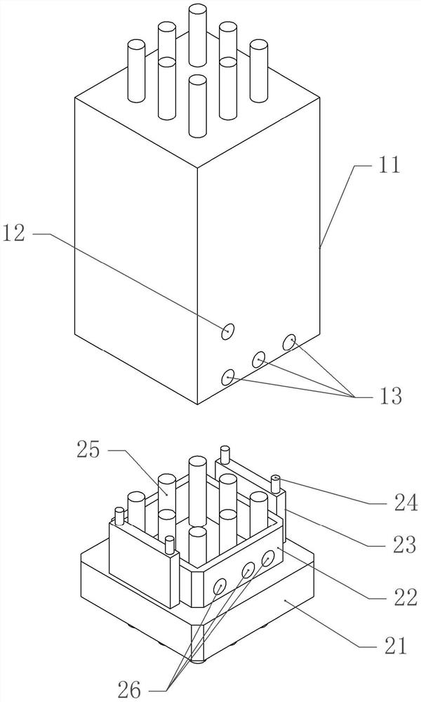
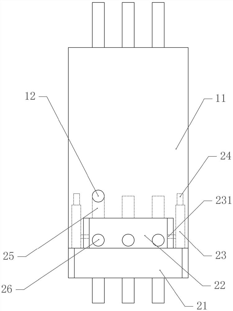
[0041] Basic as attached figure 1 , attached figure 2 , attached image 3 and Figure 4 As shown, a prefabricated reinforced concrete composite column includes a prefabricated component 11 and an assembly part. The prefabricated component 11 includes a steel bar frame 14 composed of several steel bars. The steel bar frame 14 is rectangular. The first stirrups 15 are evenly distributed vertically. In this embodiment, the first stirrups 15 are closed stirrups, and the outside and inside of the reinforcement frame 14 are filled with concrete, that is, the prefabricated components are prefabricated.
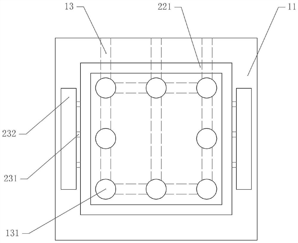
[0042] The bottom of the prefabricated component 11 is provided with a plurality of rectangular assembly holes 131 uniformly distributed, and the outer periphery of the assembly holes 131 is provided with rectangular auxiliary positioning grooves 221, and both sides of the auxiliary positioning grooves 221 are provided with positioning grooves 221. In this embodiment, the prefabr...
Embodiment 2
[0053] The difference between embodiment two and embodiment one is that, as attached Figure 5 And attached Figure 6 As shown, the reinforcement frame 14 is provided with a second stirrup 16, the second stirrup 16 is improved in this embodiment, the second stirrup 16 includes a main stirrup 161 and a secondary stirrup 165, the main stirrup 161 is A T-shaped connecting portion 162 is integrally formed, and a T-shaped groove is formed on the auxiliary stirrup 165. The main stirrup 161 is assembled through the connecting portion 162 and the groove, and the connecting portion 162 and the groove can slide relative to each other. , also includes an elastic part, the elastic part in this embodiment is a spring 164, one end of the spring 164 is welded on the secondary stirrup 165, the other end of the spring 164 is welded on the connecting part 162, and the main stirrup 161 is welded with a sleeve 163 , the sleeve 163 is welded to the auxiliary stirrup 165, that is, the sleeve 163 w...
PUM
 Abstract
Description
Claims
Application Information
 - R&D Engineer
- R&D Manager
- IP Professional
- Industry Leading Data Capabilities
- Powerful AI technology
- Patent DNA Extraction
Browse by: Latest US Patents, China's latest patents, Technical Efficacy Thesaurus, Application Domain, Technology Topic, Popular Technical Reports.
© 2024 PatSnap. All rights reserved.Legal|Privacy policy|Modern Slavery Act Transparency Statement|Sitemap|About US| Contact US: help@patsnap.com