Novel vacuum flushing device

A technology of flushing device and vacuum, applied in water supply device, grease/oily substance/float removal device, cleaning of sewer pipes, etc., can solve problems such as increasing the pressure of water storage chamber, prevent clogging, ensure fixation, and improve leakage. The effect of pressure efficiency

Pending Publication Date: 2021-09-03
TAIZHOU SHENGHE WATER TREATMENT EQUIP MFG CO LTD
View PDF1 Cites 0 Cited by
  • Summary
  • Abstract
  • Description
  • Claims
  • Application Information

AI Technical Summary

Problems solved by technology

[0005] The problem to be solved by the present invention is to drive the sealing assembly to descend through the descending movement of the lifting assembly, so that the sealing assembly seals the upper groove of the water storage chamber, which can effectively ensure that when the water storage chamber gradually forms a vacuum, the overall water storage chamber Sealing, increasing the pressure in the water storage chamber, making the water storage chamber form a vacuum, the water in the reservoir enters the water storage chamber, and the upward movement of the lifting component drives the sealing component to rise, so that the sealing component is separated from the upper groove of the water storage chamber , can greatly improve the pressure relief efficiency in the water storage chamber when the vacuum pump stops, so that the potential energy of the water body can be released instantaneously to achieve the purpose of flushing; The filter can re-filter the inhaled air to achieve the effect of double filtration and effectively prevent the clogging of the vacuum pump. A new type of vacuum flushing device

Method used


Image

  • Novel vacuum flushing device
  • Novel vacuum flushing device
  • Novel vacuum flushing device

Examples


Embodiment Construction

[0022] The present invention will be further explained below in conjunction with the accompanying drawings and embodiments.

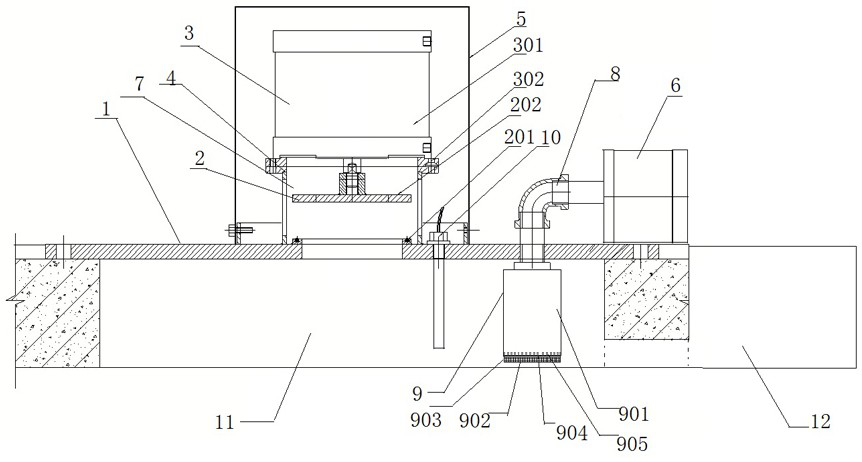
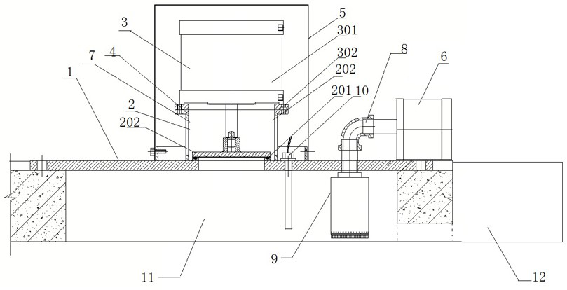
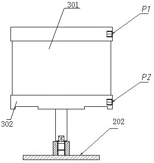
[0023] A novel vacuum flushing device, comprising a base 1 fixed on the top of the water storage chamber and a vacuum pump 6 arranged on the base to suck air, one end of the vacuum pump 6 is connected to a vacuum pipeline 8, and the other end of the vacuum pipeline 8 is provided In the water storage chamber, the upper end of the base 1 is provided with a pressure increasing and releasing mechanism, and the pressure increasing and releasing mechanism includes a sealing assembly 2 and a lifting assembly 3, the sealing assembly 2 is arranged on the upper end of the base 1, and the upper end of the sealing assembly 2 is provided There is a lifting assembly 3, the lifting part of the lifting assembly 3 is fixedly connected with the sealing assembly 2 so as to drive it to move up and down, the connecting parts at both ends of the lifting assembly 3 are fixedly...


PUM


Abstract

The invention discloses a novel vacuum flushing device. The novel vacuum flushing device comprises a base fixed to the top of a water storage chamber and a vacuum pump arranged on the base and used for sucking air; one end of the vacuum pump is connected with a vacuumizing pipeline, and the other end of the vacuumizing pipeline is arranged in the water storage chamber; a pressure increasing and relieving mechanism is arranged at the upper end of the base and comprises a sealing assembly and a lifting assembly; the sealing assembly is driven to descend through descending motion of the lifting assembly, so that the sealing assembly seals an opening groove in the upper portion of the water storage chamber, the overall sealing performance of the water storage chamber is guaranteed when the water storage chamber is vacuumized, the pressure in the water storage chamber is increased, the water storage chamber is vacuumized, water in a water storage pool enters the water storage chamber, the sealing assembly is driven to ascend through ascending motion of the lifting assembly, the sealing assembly is separated from the opening groove in the upper portion of the water storage chamber, when the vacuum pump stops, the pressure relieving efficiency in the water storage chamber is greatly improved, and the potential energy of water is released instantly to achieve the flushing purpose; and an air filtering assembly can effectively prevent blockage in the vacuum pump.

Description

technical field [0001] The invention relates to the technical field of sludge deposition cleaning at the bottom of a reservoir, in particular to a novel vacuum flushing device. Background technique [0002] With the development of social economy and the continuous improvement of living standards, people have put forward higher requirements for the living environment. China has proposed corresponding solutions to adapt to environmental changes and deal with natural disasters caused by rain. Sponge city is a new conceptual measure of stormwater management. Aiming at the purpose of storing rainwater and flood water for infiltration, use, and discharge, a new technology and new method of water storage or collection pool are proposed. [0003] Because the rainwater contains a large amount of suspended solids and particulate matter, etc., these pollutants in the water will be deposited at the bottom of the pool after passing through the reservoir or the sump. Long-term depositio...

Claims


Application Information

Patent Timeline
Patent Type & Authority Applications(China)
IPC IPC(8): E03F9/00E03F7/00E03F5/14E03F5/10
CPCE03F9/00E03F9/007E03F7/00E03F5/14E03F5/10E03F5/105E03F5/108
Inventor 顾维扬姚金路吉春美章建国林月云
Owner TAIZHOU SHENGHE WATER TREATMENT EQUIP MFG CO LTD
Why Eureka
Try Eureka