Machining method for bypass branch pipe of pipeline

A processing method and bypass technology, applied in the field of pipe fittings processing, can solve the problems of poor precision, high processing difficulty and low efficiency, and achieve the effects of improving precision and quality, good uniformity and high efficiency

Pending Publication Date: 2021-09-03
四川龙立可不锈钢管业有限公司
View PDF10 Cites 2 Cited by
  • Summary
  • Abstract
  • Description
  • Claims
  • Application Information

AI Technical Summary

Problems solved by technology

[0005] The technical problem to be solved and the technical task proposed by the present invention are to improve the prior art, provide a processing method for the bypass branch pipe of the pipeline, and solve the problem of using a tapered reamer to drill the side wall hole of the main pipeline in the current technology. Hole expansion forming, difficult processing, low efficiency and poor precision

Method used


Image

  • Machining method for bypass branch pipe of pipeline
  • Machining method for bypass branch pipe of pipeline
  • Machining method for bypass branch pipe of pipeline

Examples


Embodiment 1

[0033] A method for processing a bypass branch pipe of a pipeline mainly includes the following steps:

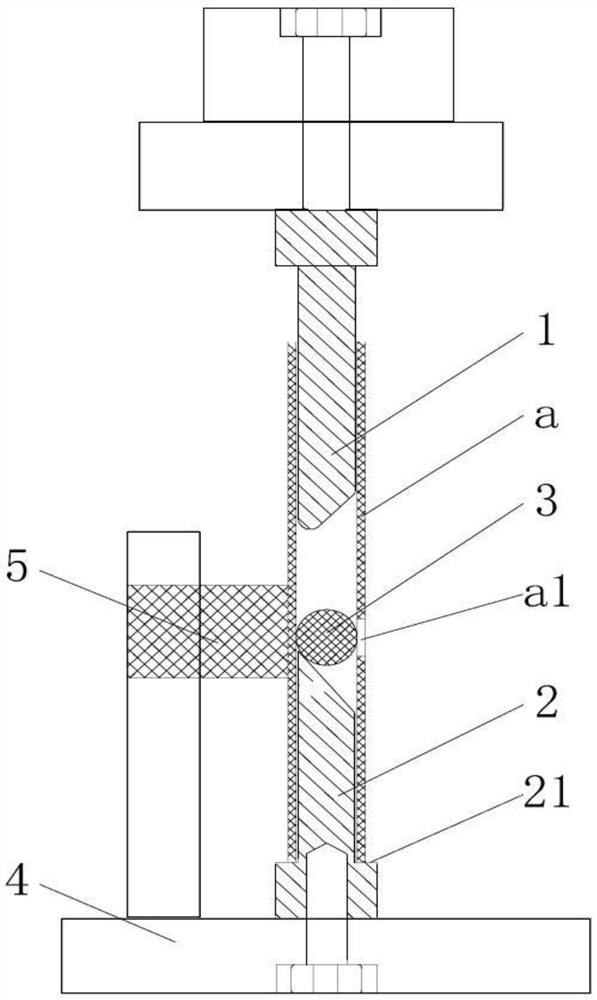
[0034] A. Open a hole at a predetermined position on the wall of the main pipe a to form a side wall hole a1;

[0035] The side wall hole a1 can be processed by cutting or punching;

[0036] When using the punching method to process the side wall hole a1, the punching die with the slot hole is placed into the main pipe a, and the slot hole of the punching die is facing the position where the side wall hole a1 needs to be processed in the main pipe a, and The punching die matched with the punching die is driven by the stamping mechanism to punch the punching die from the outside of the pipe wall of the main pipe a, and the punching die passes through the pipe wall of the main pipe a and enters the punching die to obtain the side wall hole a1, then the punching die exits in reverse and the punching die exits from the inside of the main pipe a;

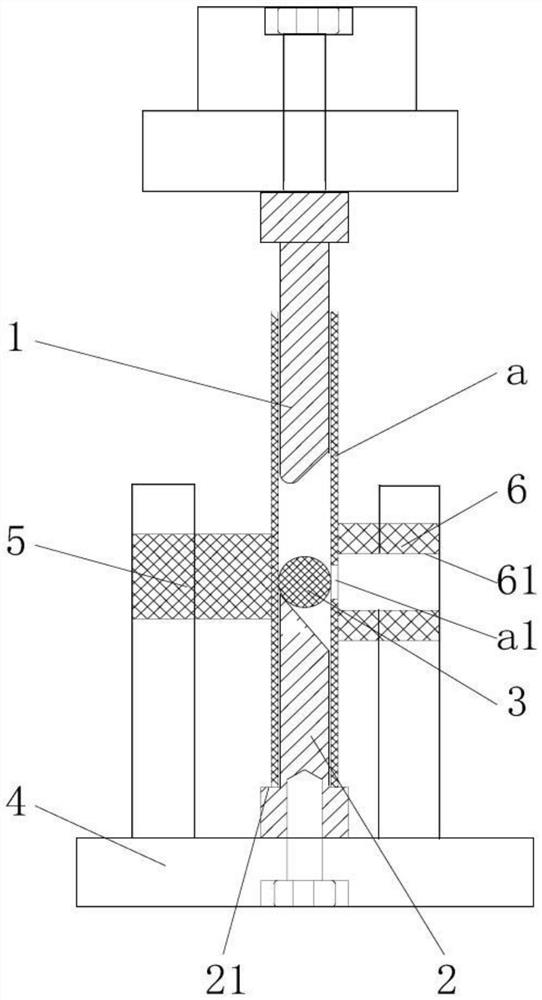
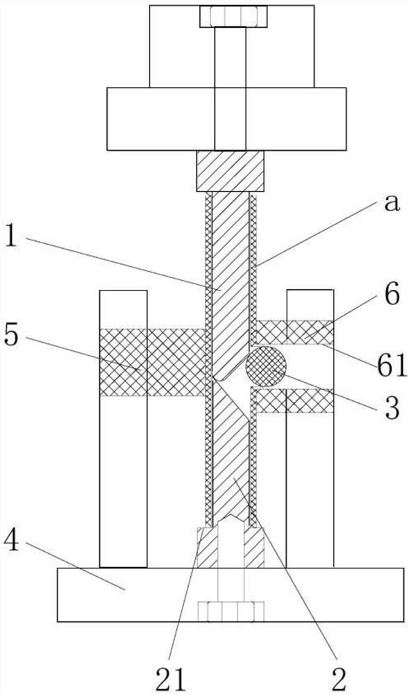
[0037] B. Reaming the side wal...

Embodiment 2

[0044] A method for processing a bypass branch pipe of a pipeline mainly includes the following steps:

[0045] A. Open a hole at a predetermined position on the wall of the main pipe a to form a side wall hole a1;

[0046] The side wall hole a1 can be processed by cutting or punching;

[0047] When using the punching method to process the side wall hole a1, the punching die with the slot hole is placed into the main pipe a, and the slot hole of the punching die is facing the position where the side wall hole a1 needs to be processed in the main pipe a, and The punching die matched with the punching die is driven by the stamping mechanism to punch the punching die from the outside of the pipe wall of the main pipe a, and the punching die passes through the pipe wall of the main pipe a and enters the punching die to obtain the side wall hole a1, then the punching die exits in reverse and the punching die exits from the inside of the main pipe a;

[0048] B. Reaming the side w...


PUM


Abstract

The invention discloses a machining method for a bypass branch pipe of a pipeline. A hole is formed in the preset position of the pipe wall of a main pipeline to form a side wall hole, a spherical hole expanding die body is arranged in the main pipeline, a first punch and a second punch are inserted into the two ends of the main pipeline correspondingly, the front end, inserted into the main pipeline, of at least one of the first punch and the second punch is an inclined face inclining relative to the axial direction of the main pipeline, the first punch and the second punch are driven to get close in the main pipeline and extrude and push the hole expanding die body to move towards the side wall hole, the hole expanding die body conducts hole expanding forming machining on the side wall hole to obtain a flanged hole, and an extending pipe is connected to the flanged hole to form the bypass branch pipe. According to the machining method, the spherical hole expanding die body is adopted for hole expanding forming, the hole expanding forming precision and quality are improved, operation is easy and convenient, efficiency is high, full-automatic mechanical production can be achieved, the labor intensity is lowered, and time and labor are saved.

Description

[0001] This application is a divisional application with the invention name of the parent case "A processing method for bypass branch pipes of pipelines"; the application number of the parent case is: 201910131892.1; the filing date of the parent case is: 2019.02.22 technical field [0002] The invention relates to the technical field of pipe fitting processing, in particular to a processing method for bypass branch pipes of pipelines. Background technique [0003] In addition to direct integral molding, there is also a way to connect bypass branch pipes on the main pipe to make tee pipes, four-way pipes, etc. The traditional processing method is to open a small hole in the main pipe, and then place the pipe inside the main pipe. A tapered reamer, the small end of the reamer is facing the small hole, and then the small end of the reamer is connected to the force applying mechanism located outside the small hole, and the force applying mechanism pulls the reamer out of the sma...

Claims


Application Information

Patent Timeline
Patent Type & Authority Applications(China)
IPC IPC(8): B21C37/29
CPCB21C37/29
Inventor 肖波陶航敬维向本成叶永红
Owner 四川龙立可不锈钢管业有限公司
Why Eureka
Try Eureka