Cotton piece storage device

A technology for storing devices and brain cotton sheets, which is applied in the field of neurosurgery, can solve the problems of small storage racks, large occupied space, and affecting the convenience of surgery, and achieve the effect of increasing storage capacity and small volume

Active Publication Date: 2021-09-03
THE FIRST PEOPLES HOSPITAL OF NANTONG
View PDF22 Cites 0 Cited by
  • Summary
  • Abstract
  • Description
  • Claims
  • Application Information

AI Technical Summary

Problems solved by technology

[0004] In 2010, in the article "Experience of Applying Detachable and Adjustable Brain Cotton Patch Hanger" on pages 715-716 of Volume 34 of Heilongjiang Medical Issue No. For hanging, if there are enough brain pads that can be hung, then enough nailed steel bars are needed, and the hanger as a whole is large and takes up a lot of space, which affects the convenience of the operation and the storage capacity of the brain pads. There is a contradiction between the development of more and more racks and the development of racks as a whole tends to be smaller, it is difficult to achieve the purpose of sufficient storage capacity and the storage rack itself is small

Method used


Image

  • Cotton piece storage device
  • Cotton piece storage device
  • Cotton piece storage device

Examples


no. 1 example

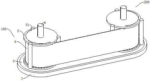
[0032] First example: see figure 1 , a storage device for brain cotton sheets, comprising a bottom frame 1 and a belt-type storage piece 4, a first winding structure 100 is installed at the upper left portion of the bottom frame 1, and a second winding structure 200 is installed at the upper right portion of the bottom frame 1, The first winding structure 100 includes a rotating rod 6 vertically penetrating the bottom frame 1 and the rotating rod 6 rotates horizontally relative to the bottom frame 1. The second winding structure 200 has the same structure as the first winding structure 100. The belt storage part 4 The two ends are respectively connected to the ring-shaped outer ends of the two rotating rods 6 , and the edge portions on both sides of the belt-type storage part 4 are respectively wound outside the two rotating rods 6 .

[0033] The belt-type storage part 4 between the first winding structure 100 and the second winding structure 200 is in a vertically flattened s...

no. 2 example

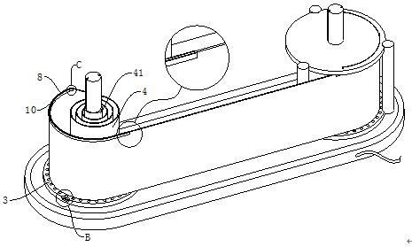
[0036] Second example: see Figure 2-Figure 4 , the bottom end of the liquid-holding tank is fixed with the second clamping block 63, and the inside of the sponge 2 is provided with a first clamping slot that is clamped with the second clamping block 63, and the upper end of the second clamping block 63 is fixed with the first clamping block 62, and the second clamping block 63 The upper end is provided with a bottom circular plate 3, and the second clamping block 63 is used to support the bottom circular plate 3. The inside of the bottom circular plate 3 is provided with a second draw-in slot that is clamped with the first clamping block 62. The second clamping block 63 and the first clamping block 63 The blocks 62 are all rotatably set on the ring-shaped outer end of the rotating rod 6, and at least two leakage holes 31 are evenly opened inside the bottom circular plate 3, and the belt-type storage part 4 is movably installed on the upper end of the bottom circular plate 3, a...

no. 3 example

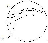
[0039] Third embodiment: see Figure 4 , Figure 6-Figure 10 , the upper end of the outer limit plate 8 is fixed with a clamping column 81, and the clamping column 81 is set to more than two; the inside of the upper limit plate 5 has a round hole, and the clamping column 81 runs through the circular hole up and down; Three card grooves, the upper end of the upper limit plate 5 is slidingly installed with a semicircle clamping block 91, the upper end of the upper limit plate 5 is provided with a slide groove, the inside of the slide groove is provided with a slide rail, and the semicircle clamp block 91 is installed on the slide rail to facilitate the movement of the semicircle clamp block 91 left and right. The clamping block 91 is clamped inside the third draw-in groove, and the clamping member includes an elastic rod 9, which is fixedly connected with more than two semicircular clamping blocks 91, and the strap storage part 4 is detachably connected with the rotating rod 6, ...


PUM


Abstract

The invention relates to the technical field of neurosurgery, in particular to a cotton piece storage device. The cotton piece storage device comprises a bottom frame and a belt type storage part, wherein a first winding structure and a second winding structure are arranged at the upper end of the bottom frame; the first winding structure comprises a rotating rod vertically penetrating through the bottom frame; the rotating rod horizontally rotates relative to the bottom frame; the structure of the second winding structure is the same as the structure of the first winding structure; the two ends of the belt type storage part are respectively connected to the annular outer ends of the two rotating rods; the belt type storage part can be used for storing a plurality of cotton pieces; the part, positioned between the first winding structure and the second winding structure, of the belt type storage part can be adjusted by rotating the rotating rods; the belt type storage piece part at which the cotton pieces are stored is wound; in addition, the part at which the cotton pieces are not stored is moved to a position between the first winding structure and the second winding structure; through the design, the requirement of storing a large number of cotton pieces at the same time is met; in addition, the whole storage device is small; and the convenience in an operation is not affected.

Description

technical field [0001] The invention relates to a storage device for brain cotton sheets, which belongs to the technical field of neurosurgery. Background technique [0002] Brain cotton sheet is the most commonly used and most common hemostatic material in neurosurgery and spinal surgery. It is mainly used for intraoperative hemostasis, keeping the operative field clear, and protecting brain tissue, cranial nerves, and spinal nerves from being damaged during surgery. [0003] Neurosurgery and spinal surgery takes a relatively long time, especially complex neurosurgery operations, which involve more bleeding and a large amount of brain cotton sheets. When the amount of bleeding is large, dozens or even hundreds of brain cotton sheets are needed. Therefore, the intraoperative management of brain cotton sheets is the most important thing in the management of small objects in the operating room. [0004] In 2010, in the article "Experience of Applying Detachable and Adjustabl...

Claims


Application Information

Patent Timeline
Patent Type & Authority Applications(China)
IPC IPC(8): A61F15/00
CPCA61F15/001
Inventor 王学建陈亨顾华杰
Owner THE FIRST PEOPLES HOSPITAL OF NANTONG
Why Eureka
Try Eureka