
Power battery cooling assembly

A technology for cooling components and power batteries, applied in battery pack components, electrical components, secondary batteries, etc., can solve the problems of connection and use of different numbers of power batteries, poor adaptability, etc. Avoid up and down bumps, improve the effect of adaptability

Pending Publication Date: 2021-08-31
李敬友
View PDF14 Cites 0 Cited by
  • Summary
  • Abstract
  • Description
  • Claims
  • Application Information

AI Technical Summary

Problems solved by technology

During the use of the power battery, a large amount of heat will be emitted, which needs to be discharged in time, otherwise there will be safety hazards
[0003] This application improves the prior art. The cooling assembly in the prior art can only be limited to a power battery of a single size when installing the power battery, and cannot be applied to the installation of power batteries of different widths. It is also impossible to adapt different numbers of power batteries for connection and use according to the actual situation, and the adaptability is not good

Method used


Image

  • Power battery cooling assembly
  • Power battery cooling assembly
  • Power battery cooling assembly

Examples


Embodiment 1

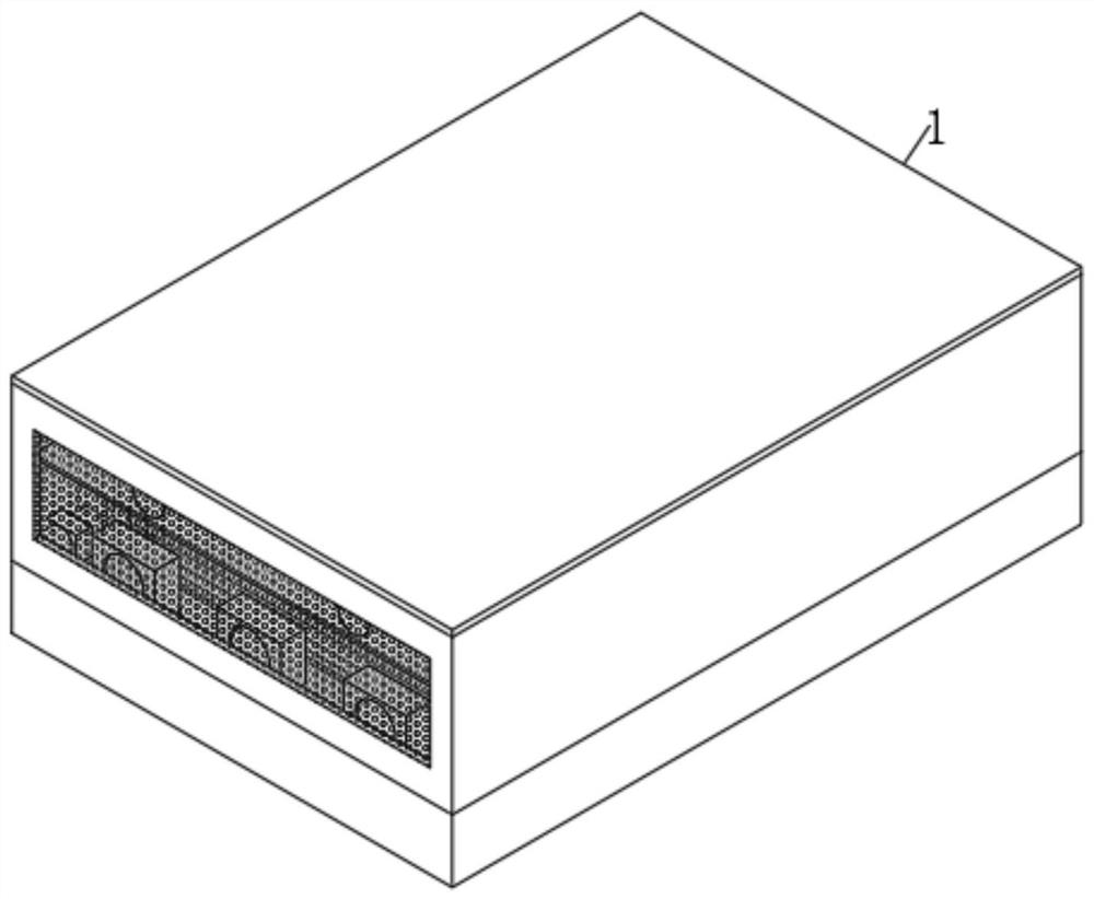
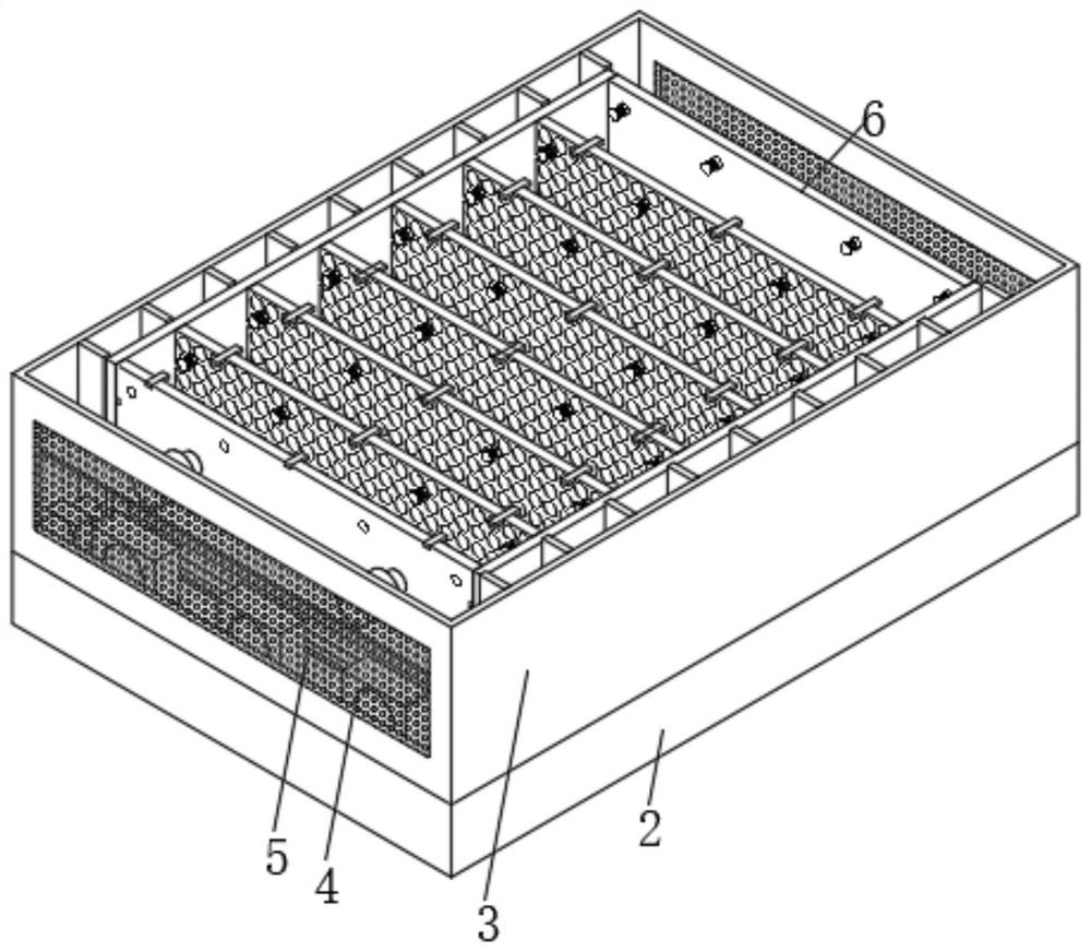
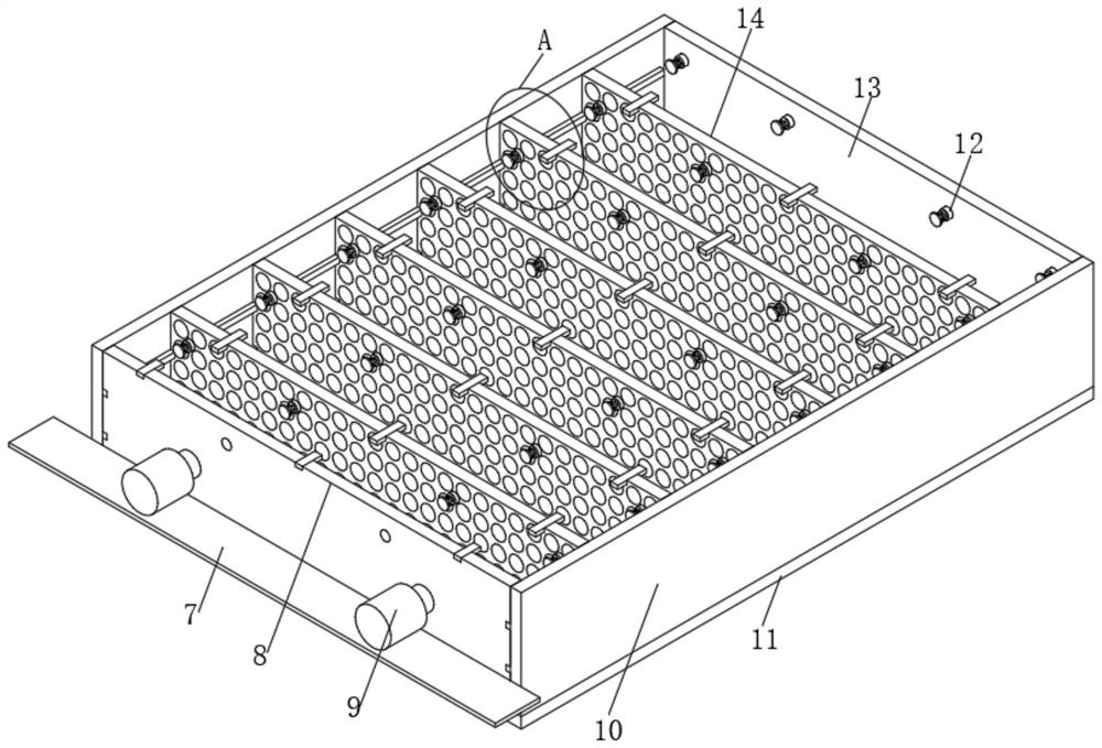
[0042] see Figure 1-8 , a cooling assembly for a power battery, including a cooling assembly main body 1, a battery storage part 6 is arranged inside the cooling assembly main body 1, and the battery storage part 6 includes a mesh bottom plate 11, and two sides are fixedly installed on the top of the mesh bottom plate 11. Vertical plate one 10, one side of the top of the mesh bottom plate 11 is fixedly installed with a side plate two 13, one side of the side plate two 13 is inlaid with eight buffer limiters one 12, and the other side of the top of the mesh bottom plate 11 is slidingly installed There is a movable limiting extruded structure 8, and a plurality of middle isolation limiting structures 14 are slidably installed between the opposite surfaces of the two side vertical plates 10.

[0043] After the power battery is placed inside the battery storage chamber, the outermost power battery is pushed through the movable limiting extrusion structure 8, and the power battery...

Embodiment 2

[0055] see Figure 1-8 , on the basis of Embodiment 1, the present invention provides a technical solution: the cooling assembly main body 1 also includes a water storage tank 2, the top of the water storage tank 2 is fixedly installed with a hollow outer frame 3, and the top of the hollow outer frame 3 is screwed A top cover is fixedly installed, and both sides of the hollow outer frame 3 are provided with inlet and outlet air cooling outlets 4, and the inside of the inlet and outlet air cooling outlets 4 is fixedly installed with dust filter screens 5, and the top of the water storage tank 2 is staggered. Time-delay partition one 19 and time-delay partition two 25, one side of time-delay partition one 19 runs through and is provided with communicating port 21, and the top of delay partition one 19 and delay partition two 25 is all fixedly installed with two Vertical bar 18, one side of water storage tank 2 tops are fixedly equipped with three axial flow fans 28.

[0056] Th...


PUM


Abstract

The invention discloses a power battery cooling assembly, which comprises a cooling assembly main body. A battery storage part is arranged in the cooling assembly main body, the battery storage part comprises a mesh bottom plate, two first side vertical plates are fixedly installed on the top of the mesh bottom plate, a second side plate is fixedly installed on one side of the top of the mesh bottom plate, and eight first buffering limiting pieces are installed on one side of the second side plate in an embedded mode. According to the power battery cooling assembly, the movable limiting and extruding structure pushes the outermost power batteries, the power batteries are tightly extruded together to be fixed through the effect of extruding one by one, the power batteries can be conveniently assembled and disassembled, and meanwhile, due to the fact that the middle isolating and limiting structure is in a movable state, the distance between the two middle isolating and limiting structures can be adjusted, so that the battery storage part can be used for clamping power batteries with different width sizes at the same time, and the adaptability of the assembly can be improved.

Description

technical field [0001] The invention relates to the field of a power battery, in particular to a cooling assembly of a power battery. Background technique [0002] The power battery is the power source that provides the power source for the tool, and mostly refers to the battery that provides power for electric vehicles, electric trains, electric bicycles, and golf carts. It is mainly different from the starter battery used to start the car engine. Valve-port sealed lead-acid batteries, open tubular lead-acid batteries and lithium iron phosphate batteries are mostly used. During the use of the power battery, a large amount of heat will be emitted, which needs to be discharged in time, otherwise there will be safety hazards. [0003] This application improves the prior art. The cooling assembly in the prior art can only be limited to a power battery of a single size when installing the power battery, and cannot be applied to the installation of power batteries of different ...

Claims


Application Information

Patent Timeline
Patent Type & Authority Applications(China)
IPC IPC(8): H01M50/249H01M50/264H01M50/267H01M50/242H01M50/24H01M10/613H01M10/625H01M10/6563H01M10/6567
CPCH01M50/249H01M50/264H01M50/267H01M50/242H01M50/24H01M10/613H01M10/625H01M10/6563H01M10/6567Y02E60/10
Inventor 不公告发明人
Owner 李敬友
Learn More