
Solar street lamp capable of automatically adjusting irradiation range

A technology of solar street lamps and irradiation range, applied in the field of solar street lamps, can solve the problems of cumbersome maintenance, high investment cost, lighting, etc., and achieve the effects of expanding the irradiation range, improving the irradiation effect, and increasing the irradiation area.

Inactive Publication Date: 2021-08-31
江苏万家耀电气集团有限公司
View PDF8 Cites 0 Cited by
  • Summary
  • Abstract
  • Description
  • Claims
  • Application Information

AI Technical Summary

Problems solved by technology

[0002] Street lamps are an important part of public facilities. At present, the power supply of existing street lamps mainly uses municipal electricity. Although it can achieve the purpose of lighting, it needs to consume a large amount of municipal electricity, and the wiring installation workload is large, and the investment cost High, and maintenance is cumbersome, can not be moved
In addition, in some areas where municipal electricity cannot be covered, street lamps cannot be used for lighting due to lack of electricity, which brings a lot of inconvenience to pedestrians.
[0003] Most of the existing solar street lights are fixed when they are in use. Due to the limited lighting range of street lights, the installation distance between street lights needs to be considered during the actual installation process to avoid large lighting blind spots of street lights in lighting. It is necessary to consider increasing the laying density of street lamps. When the laying density is high, it will lead to an increase in lighting costs.

Method used


Image

  • Solar street lamp capable of automatically adjusting irradiation range
  • Solar street lamp capable of automatically adjusting irradiation range
  • Solar street lamp capable of automatically adjusting irradiation range

Examples


Embodiment Construction

[0028] In order to make the above objects, features and advantages of the present invention more comprehensible, specific implementations of the present invention will be described in detail below in conjunction with the accompanying drawings. In the following description, numerous specific details are set forth in order to provide a thorough understanding of the present invention. However, the present invention can be implemented in many other ways different from those described herein, and those skilled in the art can make similar improvements without departing from the connotation of the present invention. Therefore, the present invention is not limited by the specific implementation disclosed below.

[0029] It should be noted that when an element is referred to as being “fixed” to another element, it can be directly on the other element or there can also be an intervening element. When an element is referred to as being "connected to" another element, it can be directly c...


PUM


Abstract

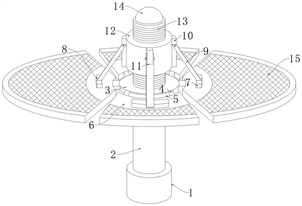
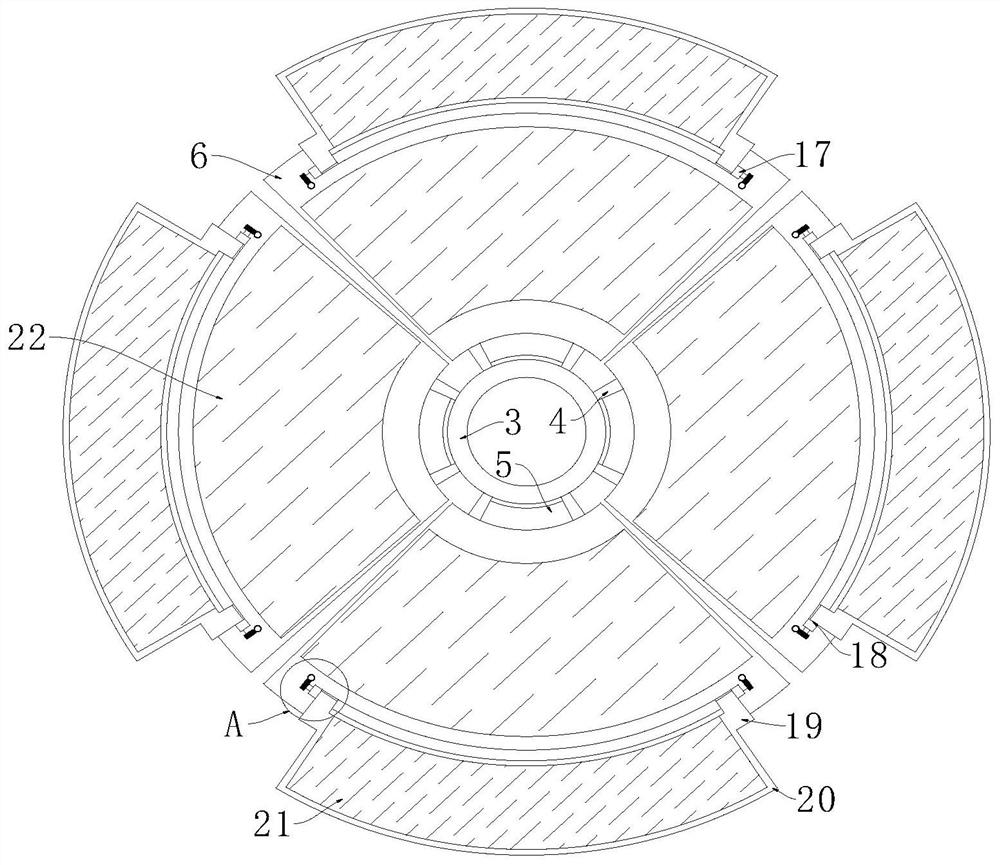
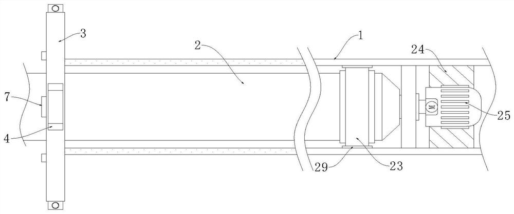
The invention discloses a solar street lamp capable of automatically adjusting the irradiation range. The solar street lamp comprises a mounting pipe, wherein a supporting disc is fixedly connected to an upper end face of the mounting pipe, a connecting rod is rotationally connected into the mounting pipe and rotationally connected with the supporting disc in a penetrating mode, and a plurality of adjusting plates are axially arranged on a side wall of the supporting disc; a supporting mechanism used for supporting the adjusting plate is arranged between the adjusting plate and the supporting disc. By arranging the adjusting plates of the fan-shaped structures, the street lamp is annularly arranged, the irradiation area of a single street lamp is increased, meanwhile, the light irradiation area of the street lamp is conveniently adjusted by rotating and adjusting the adjusting plates to form a certain angle with the horizontal direction, and light intensity of the environment where the street lamp is located is collected and determined by utilizing the light sensor; the driving motor is controlled to drive the lifting screw rod to rotate and drive the lifting pipe to lift, so the included angle between the adjusting plate and the horizontal plane is automatically adjusted, namely, the irradiation area of the street lamp is increased, and the irradiation effect is improved.

Description

technical field [0001] The invention relates to the technical field of solar street lamps, in particular to a solar street lamp that automatically adjusts the irradiation range. Background technique [0002] Street lamps are an important part of public facilities. At present, the power supply of existing street lamps mainly uses municipal electricity. Although it can achieve the purpose of lighting, it needs to consume a large amount of municipal electricity, and the wiring installation workload is large, and the investment cost High, and the maintenance is cumbersome and cannot be moved. In addition, in some areas where municipal electricity cannot be covered, street lamps cannot be used for lighting due to lack of electricity, which brings a lot of inconvenience to pedestrians. [0003] Most of the existing solar street lights are fixed when they are in use. Due to the limited lighting range of street lights, the installation distance between street lights needs to be con...

Claims


Application Information

Patent Timeline
Patent Type & Authority Applications(China)
IPC IPC(8): F21S9/03F21V23/04F21V21/30F21V21/15F21W131/103
CPCF21S9/037F21V23/0464F21V21/30F21V21/15F21W2131/103Y02B20/72
Inventor 徐凯
Owner 江苏万家耀电气集团有限公司
Learn More