
Printer plastic part forming pressing tool convenient to separate

A technology of plastic parts and printers, applied in the field of printers, can solve problems such as procrastination in the processing process, poor convenience and performance, and undesigned push at the end.

Pending Publication Date: 2021-08-31
深圳市盈顺机电设计有限公司
View PDF0 Cites 0 Cited by
  • Summary
  • Abstract
  • Description
  • Claims
  • Application Information

AI Technical Summary

Problems solved by technology

[0004] The purpose of the present invention is to provide a printer plastic parts molding press that is easy to separate from the printer, so as to solve the problem that the existing press proposed in the background technology is not equipped with a cooling structure at the end, which leads to high temperature of the parts after molding. In the case of burns, it is also not conducive to operations such as discharging, and at the same time, the end is not designed with a structure such as pushing, which leads to the inability to separate the molding materials well, resulting in a relatively procrastinated processing process and poor convenience during use.

Method used


Image

  • Printer plastic part forming pressing tool convenient to separate
  • Printer plastic part forming pressing tool convenient to separate
  • Printer plastic part forming pressing tool convenient to separate

Examples


Embodiment Construction

[0026] The following will clearly and completely describe the technical solutions in the embodiments of the present invention with reference to the accompanying drawings in the embodiments of the present invention. Obviously, the described embodiments are only some, not all, embodiments of the present invention.

[0027] In the description of the present invention, unless otherwise stated, the meaning of "plurality" is two or more; the terms "upper", "lower", "left", "right", "inner", "outer" , "front end", "rear end", "head", "tail", etc. indicate the orientation or positional relationship based on the orientation or positional relationship shown in the drawings, and are only for the convenience of describing the present invention and simplifying the description, rather than Indicates or implies that the device or element referred to must have a particular orientation, be constructed and operate in a particular orientation, and therefore should not be construed as limiting the...


PUM


Abstract

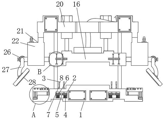
The invention relates to a printer plastic part forming pressing tool convenient to separate. The printer plastic part forming pressing tool comprises a base and side set mechanisms, side grooves are formed in the side end walls of the base, inner jacking mechanisms are arranged at the inner side ends of the side grooves, the side set mechanisms are arranged on the left end side and the right end side of the base, a middle base is installed at the upper end of the middle of the base, the front ends of the two sides of the middle base are both provided with front discs, the front ends of the front discs are provided with disc blocks, the middles of the front discs are provided with rotary adjusting lead screws in a penetrating mode, and the top end of the middle base is provided with an upper base. According to the printer plastic part forming pressing tool convenient to separate, an upper fixed plate and an assembling rod move in an embedded mode, the horizontal positions of the assembling rod and an assembling plate can be adjusted, at the moment, the position of the assembling plate can be better adjusted and controlled conveniently, the assembling plate is matched with and fixes an object, a lower penetrating rod at the bottom end of the assembling plate is clamped with a body after moving downwards, the lower penetrating rod and the assembling plate can be limited, and at the moment, the assembling plate can be controlled and used more safely and stably.

Description

technical field [0001] The invention relates to the technical field of printers, in particular to a press tool for molding plastic parts of a printer that can be easily and separated from the printer. Background technique [0002] Printer (Printer) is one of the output devices of the computer. It is used to print the results of computer processing on related media. There are three indicators to measure the quality of the printer: printing resolution, printing speed and noise. There are many types of printers, according to printing components Whether there is an impact action on the paper, it is divided into impact printers and non-impact printers, according to the structure of printed characters, it is divided into full-size character printers and dot-matrix character printers, and according to the way a line of characters is formed on paper, it is divided into serial printers As with line matrix printers, forming presses are used during processing. [0003] Because the end...

Claims


Application Information

Patent Timeline
IPC IPC(8): B29C51/44B29C51/42B29C51/30
CPCB29C51/30B29C51/42B29C51/428B29C51/44
Inventor 王诗兰韩铭琪
Owner 深圳市盈顺机电设计有限公司
Learn More