
Ultrasonic probe attitude detection device and method

An ultrasonic probe and detection device technology, applied in the directions of diagnostic probe accessories, ultrasonic/sonic/infrasonic diagnosis, sonic diagnosis, etc., can solve problems such as high cost, inaccurate measurement, affecting work, etc., to avoid clinical misdiagnosis and satisfy comfortable experience demand, the effect of eliminating the impact

Active Publication Date: 2021-08-31
苏州晟智医疗科技有限公司
View PDF15 Cites 0 Cited by
  • Summary
  • Abstract
  • Description
  • Claims
  • Application Information

AI Technical Summary

Problems solved by technology

[0002] Clinically, ultrasonic Doppler image monitoring equipment is used to monitor the patient's physical signs, but during the long-term monitoring process, due to the voluntary or involuntary movement of the patient's body parts, non-disease-induced changes will occur in the ultrasonic Doppler image, and measurement errors may occur. Accurate problem, but can not judge in time whether it is the problem of the patient's blood flow status or the problem of the fixed probe, which may cause clinical misdiagnosis
[0003] In order to solve the above problems in the prior art, the pressure sensor is arranged on the surface of the probe, and the bonding state of the monitoring probe and the skin is realized through the pressure sensor, but the pressure sensor arranged on the surface of the probe will inevitably affect the work of the probe at the pasted part; Some existing technologies use rigid fixing devices to firmly fix the probe on the skin surface of the human body to be monitored. On the one hand, the rigid fixing method is not conducive to the humanized experience of the patient. On the other hand, the rigid fixing method cannot effectively detect the probe on the surface of different parts. attitude
In addition, there are some methods regardless of cost, such as using infrared distance sensors, image scanning of bonding parts, and through complex training algorithms and training models, to finally judge the posture of the ultrasonic probe. The equipment is complicated and the cost is too high

Method used


Image

  • Ultrasonic probe attitude detection device and method
  • Ultrasonic probe attitude detection device and method

Examples


no. 1 example

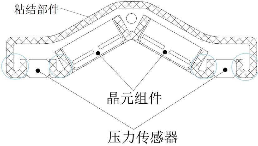
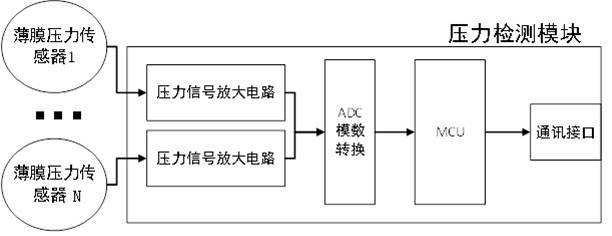
[0021] According to the first embodiment of the present invention, reference is made to the accompanying figure 1 , to provide an ultrasonic probe attitude detection device, comprising: at least two thin film pressure sensors, an ultrasonic probe crystal element assembly, and a bonding component.

[0022] Among them, the crystal element component of the ultrasonic probe is the main part of the ultrasonic probe, which is used to contact the human skin, detect physiological parameters such as blood flow and blood oxygen in the skin, and communicate with the monitoring computer through a data link to implement clinical monitoring.

[0023] On the one hand, the adhesive part is used to place the thin film pressure sensor and the ultrasonic probe element assembly, so that they can be fixed on one side of the adhesive part; Made of flexible materials to maximize the personalized experience of patients.

[0024] The thin-film pressure sensor is a thin-film sensor device made of flex...


PUM


Abstract

The invention relates to an ultrasonic probe attitude detection device and method. The ultrasonic probe attitude detection device comprises at least two film pressure sensors, an ultrasonic probe wafer assembly and a bonding part, wherein the ultrasonic probe wafer assembly and the at least two film pressure sensors are fixed on the same side of the bonding part, and all the film pressure sensors are distributed on the outer side of the ultrasonic probe wafer assembly in a mutually-isolated manner through the bonding part. The low-cost film pressure sensors are used, and complex image recognition processing is avoided. The pressure sensors and the ultrasonic probe wafer assembly are placed in an isolated manner through the bonding part, so that the influence of the pressure sensors on the physical sign monitoring process of the ultrasonic probe patient is completely eliminated.

Description

technical field [0001] The present invention relates to the technical field of medical detection equipment, in particular, to a device and method for posture detection of an ultrasonic probe. Background technique [0002] In clinical practice, ultrasound Doppler image monitoring equipment is used to monitor patient signs, but in the long-term monitoring process, due to the voluntary or involuntary movement of the patient's body parts, the ultrasound Doppler image will undergo non-disease-caused changes, and measurement inaccuracy may occur. Accurate problem, but can not timely determine whether it is the problem of the patient's blood flow status or the problem of the fixed probe, which may lead to clinical misdiagnosis. [0003] In order to solve the above problems in the prior art, the pressure sensor is arranged on the surface of the probe, and the bonding state of the probe and the skin is monitored by the pressure sensor, but the pressure sensor arranged on the surface ...

Claims


Application Information

Patent Timeline
Patent Type & Authority Applications(China)
IPC IPC(8): A61B8/00
CPCA61B8/42A61B8/4245A61B8/4254
Inventor 丁衍何润宝
Owner 苏州晟智医疗科技有限公司
Learn More