
Irrigation emitter based on Tesla one-way valve principle and irrigation system thereof

A technology of one-way valves and sprinklers, applied in watering devices, horticultural, botanical equipment and methods, etc., can solve the problems of increasing water head loss along the way, increasing water flow energy consumption, etc., to increase local head loss and increase energy Good effect of consumption and dripping effect

Pending Publication Date: 2021-08-31
NANCHANG INST OF TECH
View PDF0 Cites 1 Cited by
  • Summary
  • Abstract
  • Description
  • Claims
  • Application Information

AI Technical Summary

Problems solved by technology

At present, the emitter mainly changes the flow channel to increase the water flow head loss along the way, thereby increasing the energy consumption of the water flow, and then achieving the purpose of steady flow.

Method used


Image

  • Irrigation emitter based on Tesla one-way valve principle and irrigation system thereof
  • Irrigation emitter based on Tesla one-way valve principle and irrigation system thereof
  • Irrigation emitter based on Tesla one-way valve principle and irrigation system thereof

Examples


Embodiment 1

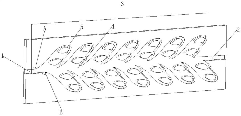
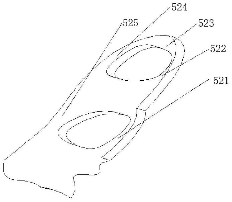
[0042] This embodiment provides an implementation of the emitter based on the Tesla check valve principle. refer to Figure 1 to Figure 3 , figure 1 It is a structural diagram of an emitter based on the Tesla check valve principle provided in the embodiment of the present application; figure 2 yesfigure 1 Structural diagram of the middle runner unit; image 3 It is the structural diagram of the capillary in 2. Such as Figure 1 to Figure 3 As shown, the emitter based on the Tesla check valve principle includes: a water inlet pipe 1, a water outlet pipe 2 and a flow channel device 3, and the flow channel device 3 includes:

[0043] Main flow pipe 4, located in the middle of the flow channel device 3;

[0044] Several flow channel units 5 are evenly connected in series and arranged oppositely on the upper and lower sides of the main flow pipe 4;

[0045] The channel unit 5 is sequentially provided with several obstacles 51 from bottom to top, and the obstacles 51 divide t...

Embodiment 2

[0071] This embodiment provides a specific implementation of the irrigation system, including the irrigator based on the principle of the Tesla check valve in Example 1, and the irrigator based on the principle of the Tesla check valve is embedded in the guide according to the requirements of the planting distance of the crops. The water hollow hose controls the central control system, and the water is sent to the filter system through the pressure pump for filtration, and finally sent to the water guide hollow hose, through the emitter based on the Tesla check valve principle in the water guide hollow hose Reduce the flow rate of water to achieve the purpose of drip irrigation for crops.


PUM


Abstract

The invention discloses an irrigation emitter based on a Tesla one-way valve principle and an irrigation system thereof, and belongs to the field of irrigation emitter manufacturing. The irrigation emitter based on the Tesla one-way valve principle comprises a water inlet pipeline, a water outlet pipeline and a flow channel device, wherein the flow channel device comprises a main flow pipeline located in the middle of the flow channel device and a plurality of flow channel units uniformly communicating in series and oppositely arranged on the upper side and the lower side of the main flow pipeline; each flow channel unit is sequentially provided with a plurality of barriers from bottom to top, and the barriers divide the flow channel units into capillary tubes and shunting capillary tubes; the capillary tubes communicate with the main flow pipeline and located on the peripheries of the barriers, each shunting capillary tube is located between the two adjacent barriers, and an inlet and an outlet of each shunting capillary tube communicate with the corresponding capillary tube. Water flow flows into the irrigation emitter based on the Tesla one-way valve principle to generate an inclined hedge and a vortex, so that the local head loss of the water flow is increased, the energy consumption of the water flow is further increased, the flow speed of the water flow is further reduced, and the irrigation uniformity is improved.

Description

technical field [0001] The application belongs to the technical field of emitter manufacturing, and in particular relates to an emitter based on the Tesla check valve principle and an irrigation system thereof. Background technique [0002] Agricultural irrigation is indispensable in the development of agriculture, among which drip irrigation is widely respected, and the water flows out in the form of dripping water to moisten the crop surface and the soil near the root system. The core part of the drip irrigation system is the emitter. The emitter achieves the effect of energy dissipation through the change of the structure and form of the flow channel, and adjusts its water flow pressure to improve the steady flow performance of the emitter, so that the water flow changes from a jet to a drip. . [0003] The change of the structure of the emitter flow channel and the selection of parameters directly affect its hydraulic performance, and the essence of the steady flow perf...

Claims


Application Information

Patent Timeline
IPC IPC(8): A01G25/00
CPCA01G25/00
Inventor 任长江钟小锋张紫慧姜仁贵鲁向晖徐胜攀万凌峰王昊
Owner NANCHANG INST OF TECH
Learn More