Cylinder head

A technology of cylinder head and cylinder, applied in the direction of cylinder head, cylinder, liquid cooling, etc., can solve the problem of insufficient cooling performance of the cylinder head, and achieve the effect of improving the cooling performance

Active Publication Date: 2021-08-27
MITSUBISHI MOTORS CORP
View PDF7 Cites 0 Cited by
  • Summary
  • Abstract
  • Description
  • Claims
  • Application Information

AI Technical Summary

Problems solved by technology

[0009] In addition, even with such a structure in which the upper passage and the lower passage are independent, the cooling performance of the cylinder head is not sufficient, and further improvement is required.

Method used


Image

  • Cylinder head
  • Cylinder head
  • Cylinder head

Examples


Embodiment Construction

[0057] Hereinafter, an embodiment of the present invention will be described in detail with reference to the drawings.

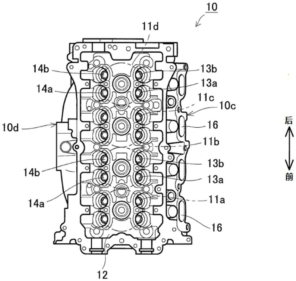
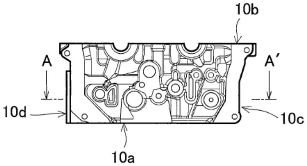
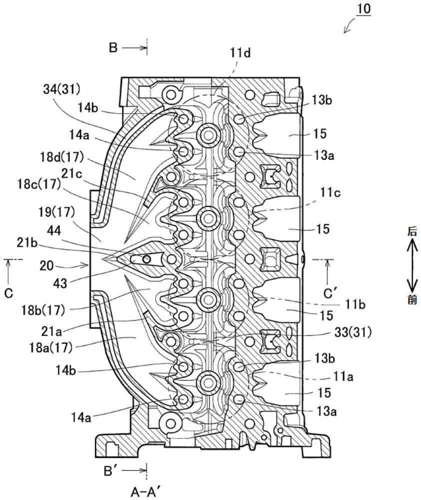
[0058] Figure 1A It is a diagram showing the upper surface of the cylinder head (surface opposite to the cylinder block mounting surface), Figure 1B It is a side view showing the front side of the cylinder head. figure 2 It is a cross-sectional view along the A-A 'line of the cylinder head. in addition, image 3 It is a perspective view showing the shape of the water-free sleeve as a shape of the sand core. Figure 4 It is a top surface view showing the shape of the water cooling. Figure 5 It is a bottom plan view showing the shape of the water cooling. in addition, Figures 6A-6B as well as Figure 7 It is a diagram for explaining the inner passage portion. Figure 6A It is a cross-sectional view along the B-B 'line of the cylinder head. Figure 6B It is an enlarged cross-sectional view near the inner channel portion. in addition, Figure 7 A cross-sectional view cor...


PUM


Abstract

A cooling water passage of this cylinder head of a multi-cylinder engine comprises: an upper passage provided above a collective exhaust port; and a lower passage facing the upper passage and provided below the collective exhaust port. The lower passage includes: a port passage part provided corresponding to the collective exhaust port; and a sub passage part extending from the downstream side of the port passage part in the row direction of cylinders, wherein the lower passage communicates with the upper passage via a sub passage part.

Description

Technical field [0001] The present disclosure relates to a cylinder head of a multi-cylinder engine, in particular, to a structure of a cooling water passage (water cooled) disposed inside the cylinder head. Background technique [0002] Conventionally, in the cylinder head of the multi-cylinder engine, a plurality of exhaust ports corresponding to each of the cylinders are formed. An exhaust manifold is attached in the cylinder head, which has a plurality of exhaust passages connected to each of the exhaust ports to allow the exhaust passage to mix in the exhaust manifold. [0003] Further, in the cylinder head, a multi-cylinder engine is developed by forming an exhaust gas aggregation portion corresponding to each of the cylinders, the multi-cylinder engine configured to have a single exhaust pipe in the cylinder head. . [0004] This cylinder head is high temperature due to the influence of the internal exhaust. Therefore, in the cylinder head, a cooling water passage (water c...

Claims


Application Information

Patent Timeline
Patent Type & Authority Applications(China)
IPC IPC(8): F01P3/02F02F1/36F02F1/38F02F1/42
CPCF02F1/42F01P3/02F02F1/36F02F1/38
Inventor 松本浩一吉原昭佐野孝幸
Owner MITSUBISHI MOTORS CORP
Why Eureka
Try Eureka